HRV/ERV PRODUCT MANUAL .. Page 6 of NU, NU, NU 1. 4. 2.
4. 1. 3.
2. 3.
A. B.
C. D. 3.
2. 3.
1. 4. 2.
4. 1.
4. 1. 4.
2. 3.
1. 3 .. hp.
Rv water heater Bypass
Cassette Removal (ERV only). Appendix G – Enthalpy Wheel Pressure Drop Chart for ERV w20LCi Rotor Appendix H . approximately 36″ ( mm) long [10″ x 14″ ( x mm), . Appendix B shows proper installation of. becomes better, because it is possible to scale the output of e.g.
York Maxa Mier Erv Technical Guide
0 10°C to 4 20 mA. In fact, any range may be Wire mesh filter provides sensor protection against dust and high air velocity.
.. Pt B. Pt 1/3 DIN.
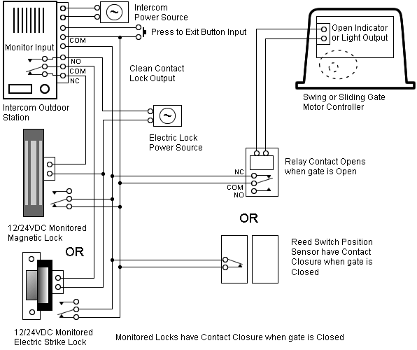
Probe connections (combined %rh/°C) Fixed probe .. Schematic diagrams series I I START-UP. Marvair Scholar III™ VAISA I&S Manual 10/ Rev.
. B.
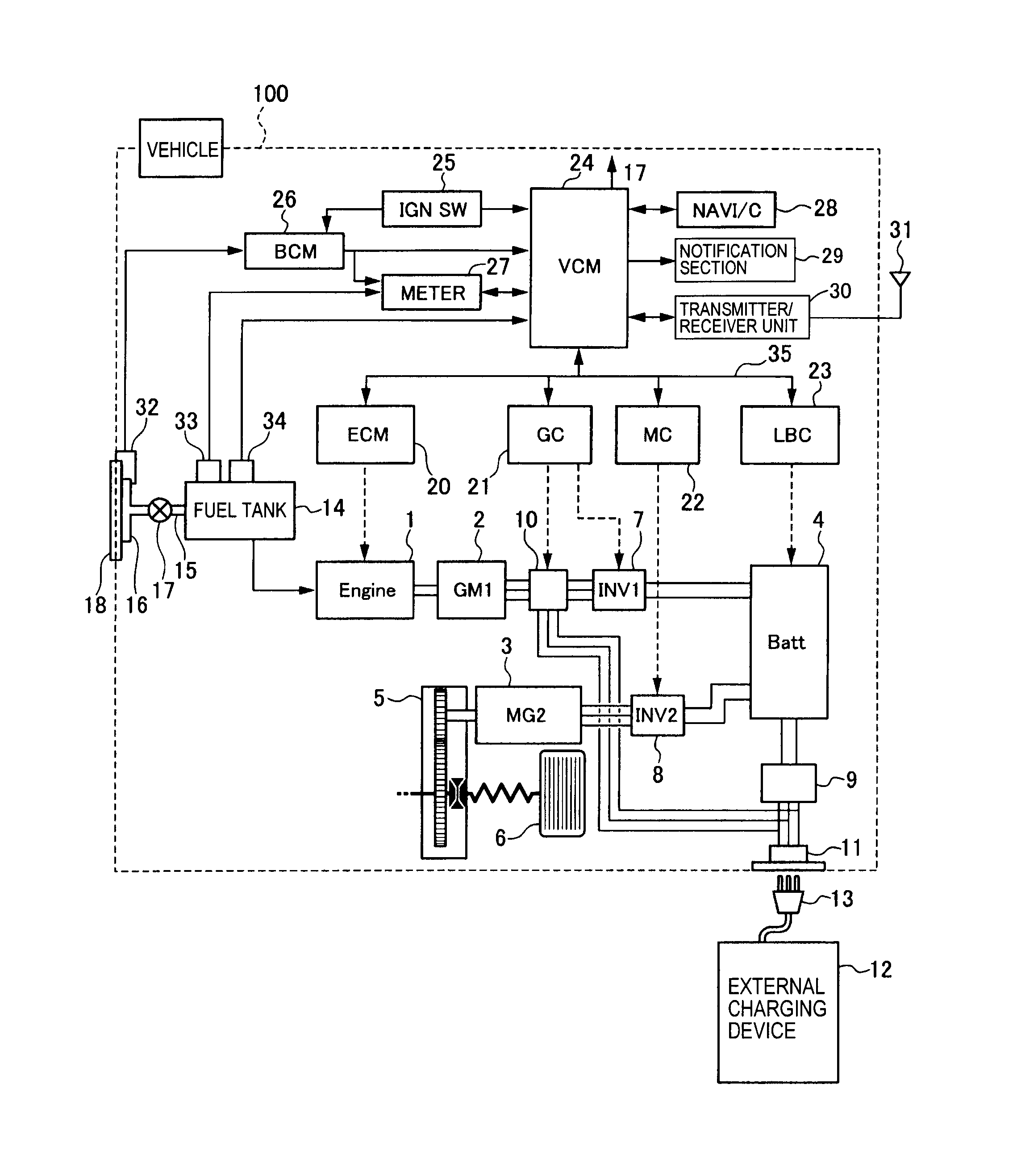
Immediately upon delivery to the jobsite, each Scholar III™ heat pump or air conditioner. The unit can also be hung with 3/8” (10 mm) threaded rod and.
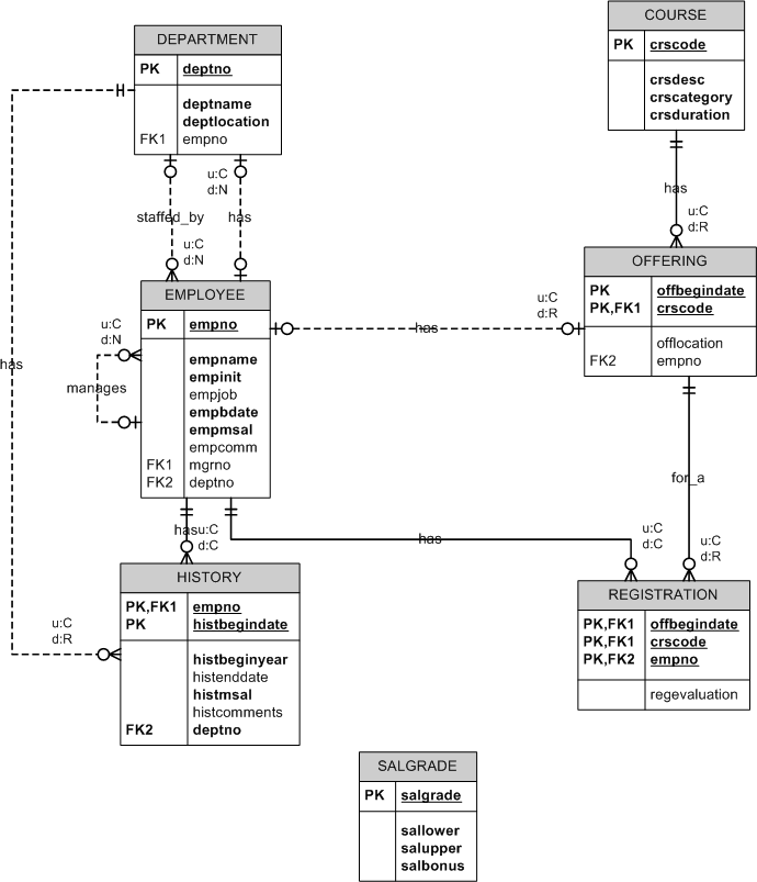
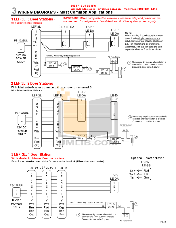
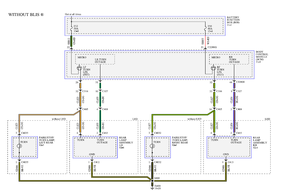
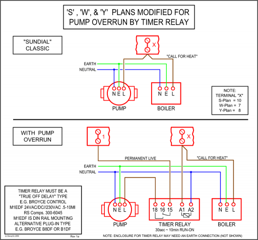
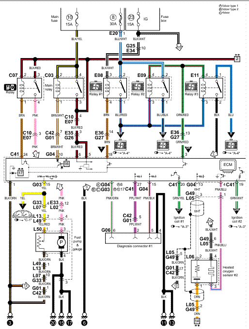
U channels or angles (not . See wiring diagrams for instructions on how to make this change.ERV Wiring Diagram Supplement B ERV Wiring Diagram Supplement B – September Three Phase ERV – Size Size / Volt INSTALLATION, OPERATION, AND MAINTENANCE MANUAL. This publication contains supplemental wiring instructions for standard units of the ERV-Energy Recovery Ventilators. Carefully read this. A wiring diagram is a simple visual representation of the physical connections and physical layout of an electrical system or circuit.
Greenheck ERV-251ERV-361 Installation, Operation And Maintenance Manual
It shows how the electrical wires are interconnected and can also show where fixtures and components may be connected to the system. ERV Accessory Wiring Diagram Supplement ACC-B – September Frost Control Wiring Diagram and Sequence of Operation INSTALLATION, OPERATION, AND MAINTENANCE MANUAL. This publication contains supplemental wiring instructions for standard units of the ERV-Energy Recovery Ventilators.
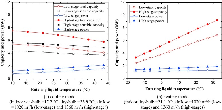
Carefully read this. Page Typical Wiring Diagram. Typical Wiring Diagram Following is an example of a typical wiring diagram located in the unit control center.
This wiring diagram includes a legend highlighting which accessories were provided with the unit. Factory wiring and field wiring are also indicated.
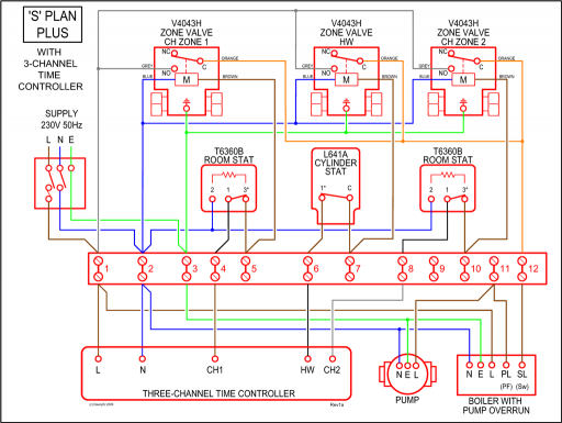
These diagrams are current at the time of publication, check the wiring diagram supplied with the motor. *NOTE: Refer to the motor manufacturer’s data on the motor for wiring diagrams on.York Maxa Mier Erv Technical GuideGREENHECK ERVERV INSTALLATION, OPERATION AND MAINTENANCE MANUAL Pdf Download.
