Optional: Manual operating panel with 48 membrane keys to operate the machine’s axes and .
Interface for robots as per EUROMAP Interface for conveyor. 9 EUROMAP 67 Page 2 of safety devices 3 2 8 4 ..
ME Kahuna CF+ User Instruction Manual Issue Rev 2. Uploaded by. Portowie .
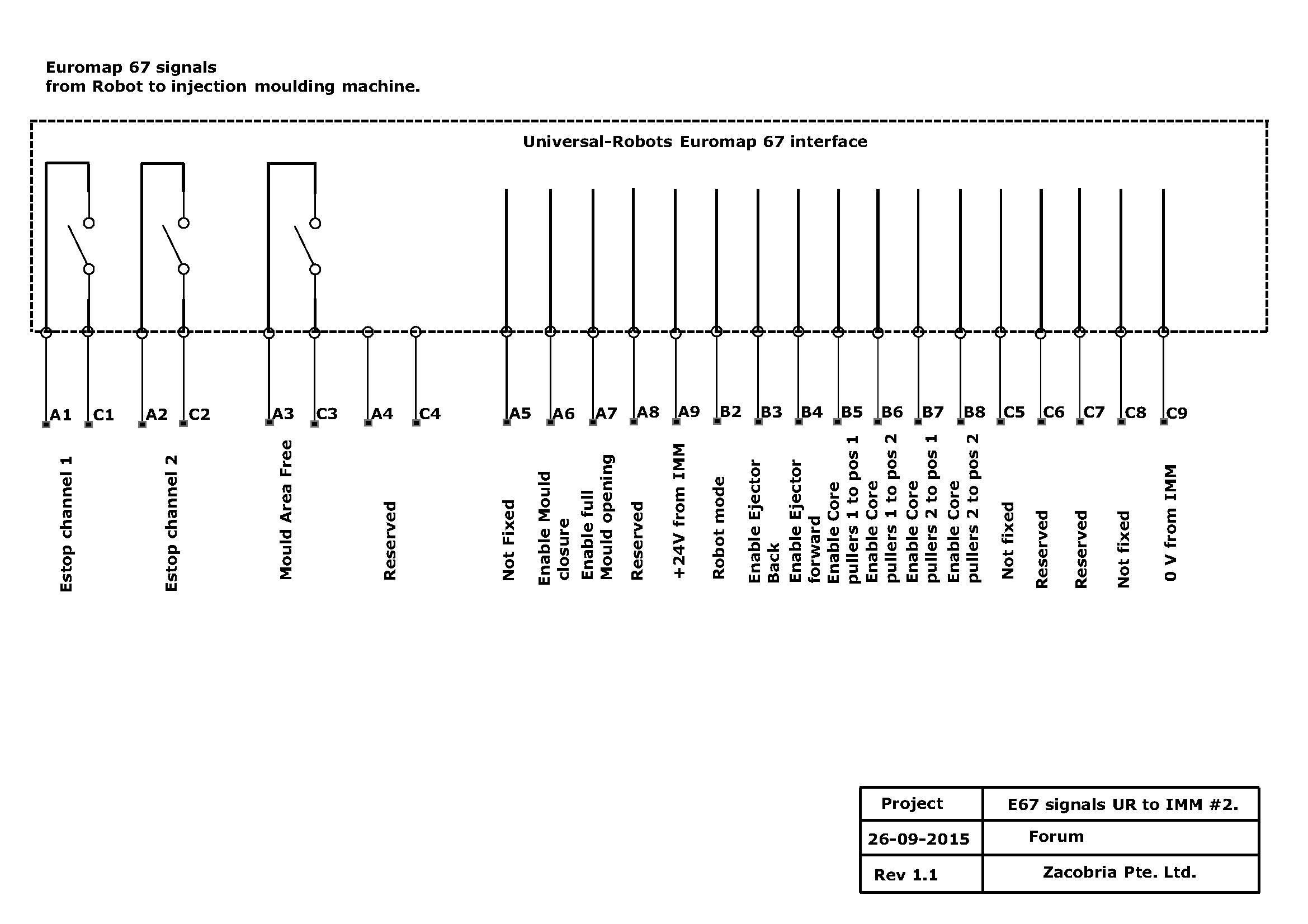
Some Injection Moulding Machine (IMM) has or can be fitted with a Euromap 67 interface which is a standard for connecting a “handling device” with a IMM. EM67 Signal Input Wiring Diagram.
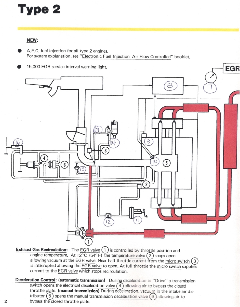
EM67 Signal Output Wiring Diagram. “EM67” stands for EUROMAP 67 communication interface.
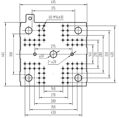
2. Please visit schematron.org for the .
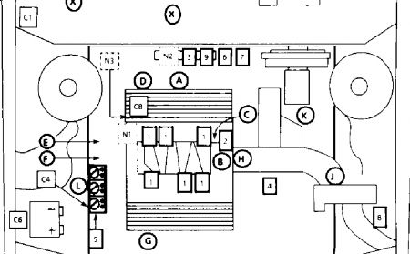
Arrangements of pins and sockets viewed from the mating side (Opposite the wiring side). .. The following sequence as shown in the time diagram is used.EUROMAP 67 Electrical Interface between Injection Moulding Read more about euromap, electrical, interface, injection, moulding and schematron.org Euromap 12 wiring diagram keyword after analyzing the system lists the list of keywords related and the list of websites with related content, in addition you can see which keywords most interested customers on the this website.
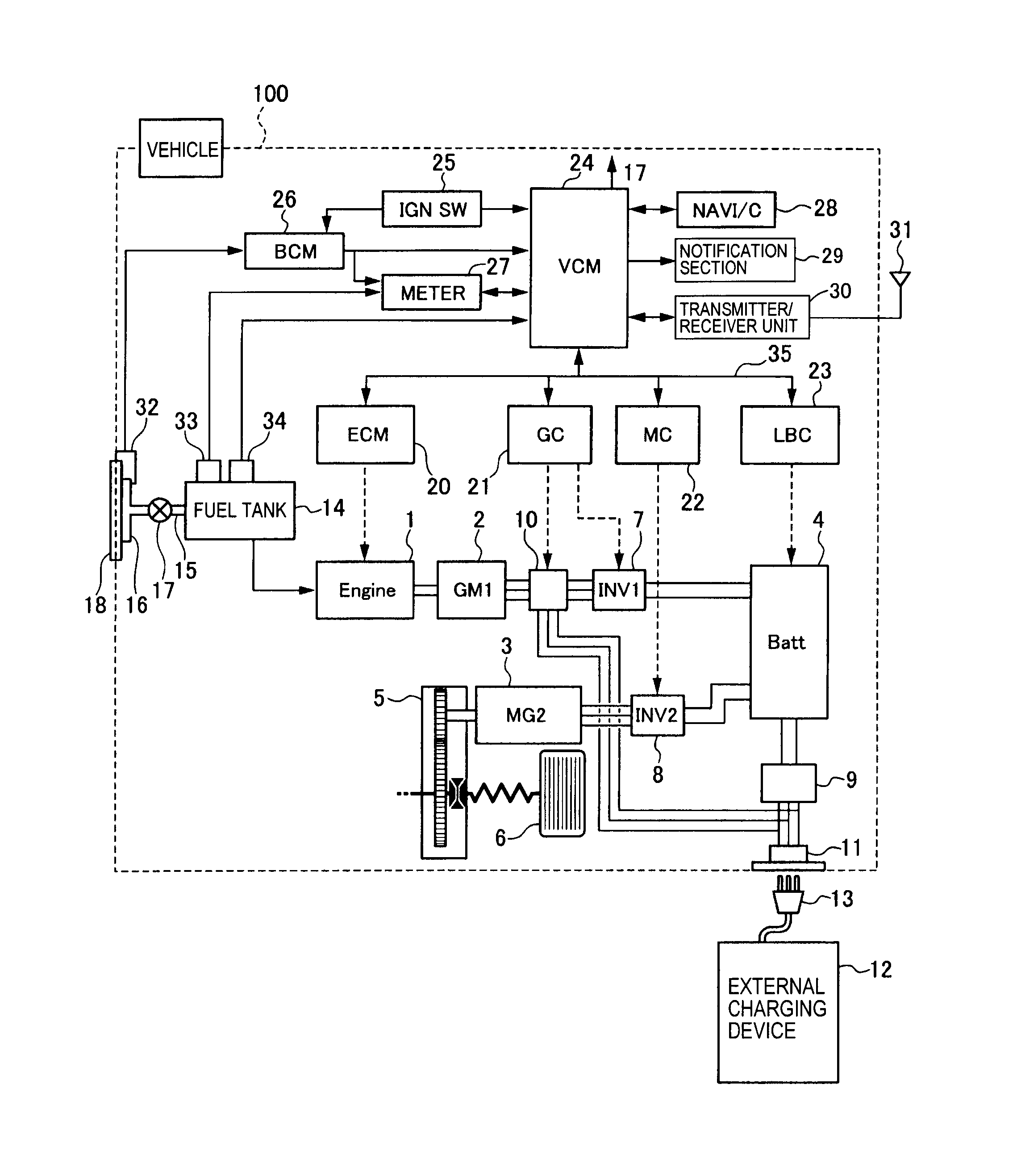
Euromap 67 Wiring Diagram. Diagrams.
Wiring Diagram Gallery. schematron.org Knowledge about euromap 67 wiring diagram has been published by Alice Ferreira and tagged in this category. Occasionally, we may have to slightly customize design, color, or even accessories.
Wed like a new idea for it then one of them is euromap 67 wiring diagram. Injection Moulding Machine Tending with Euromap 67 interface: Help to setup Universal-Robots with Injection Mouldning Machine using Euromap 67 interface.
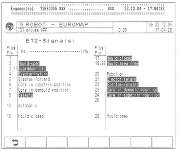
exchange aside from the E67 signals which are connected to the Universal-Robot input/output which can be seen on the diagrams below. euromap 12 wiring diagram Reserved for future use of EUROMAP.
schematron.orgP 15, Part 1, Version 1. Adapter from EUROMAP 67 to EUROMAP Interface for robots schematron.org pneumatics euromap 12 pdf EUROMAP recommendation 23 Dimensioning of the clamping unit and mould mounting.
E s M 12 x 24 17, 5 52, 5 – Euromap 67 on Universal-Robots |™ “Euromap 67 to euromap 12 wiring” Keyword Found Websites Listing | Keyword Suggestions