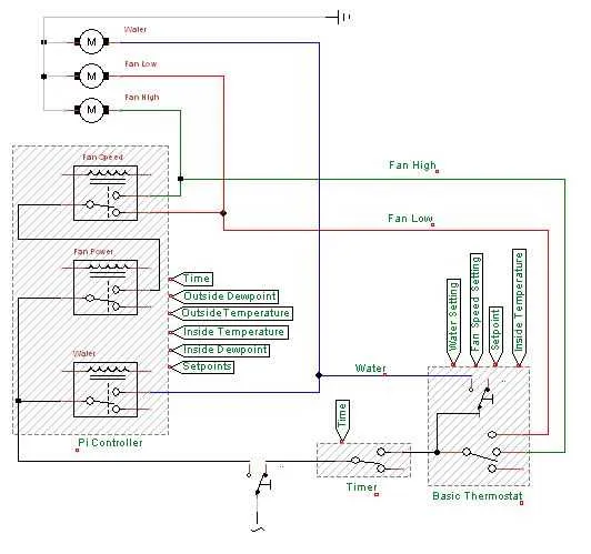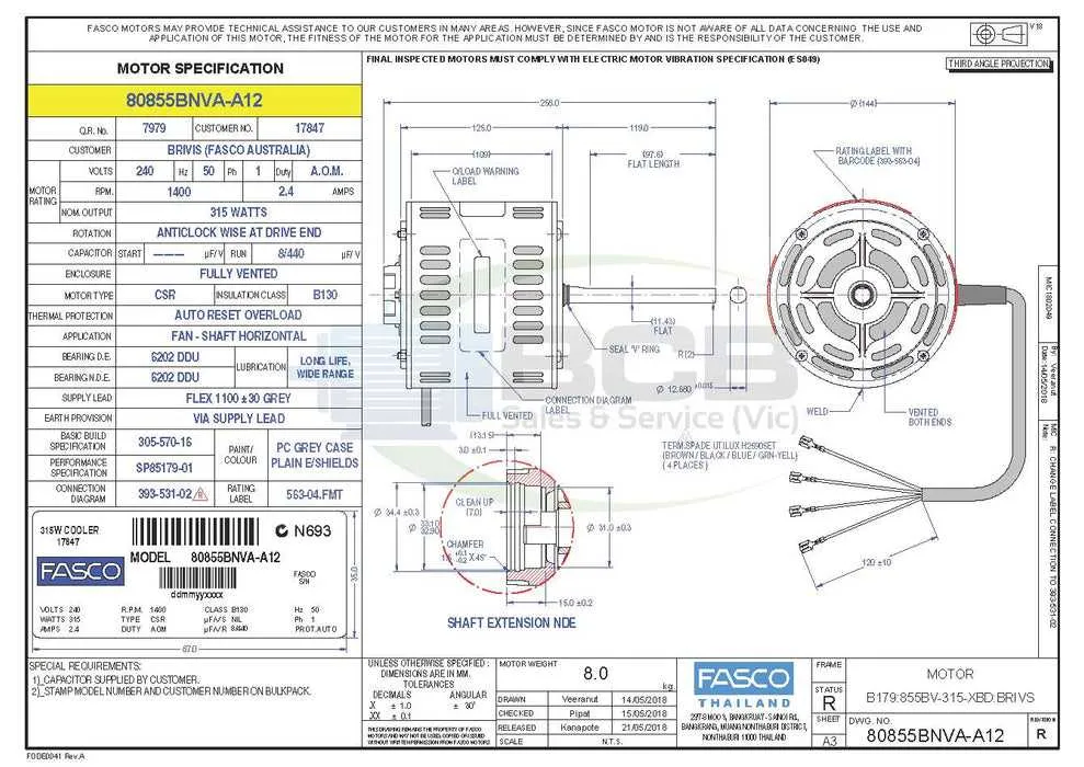
Connect the fan motor directly to the terminal marked “FAN” on the control module, ensuring the voltage rating matches the specifications on the motor label. Use insulated connectors to avoid short circuits, and verify grounding is secure before powering on the system.
For the pump mechanism, link the power lead to the relay output labeled “PUMP” or “WATER”, typically rated for 120V or 240V depending on the unit’s origin. If a float switch is present, it must be installed in series with the pump line to prevent dry running.
Use a dedicated circuit with an appropriate breaker size, usually between 15 and 20 amps, to handle startup surges and continuous load. Confirm that the controller receives uninterrupted supply by testing with a multimeter at the input terminals.
If a thermostat is included, ensure the low-voltage lines (commonly 24V AC) are correctly routed through the terminal block marked “TSTAT” or similar. Observe correct polarity when applicable, especially with digital control interfaces.
Detailed Connection Layout for Swamp Air Systems

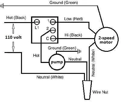
Start by identifying the terminal block on the control switch. Connect the black conductor from the power source to the “Hot” input. The white wire should link directly to the neutral bus bar, while the green or bare strand must be grounded to the chassis frame.
For fan operation, route the brown line to the “High” setting and the orange to the “Low” terminal. Tie both to the fan motor accordingly. The pump motor generally connects via a blue wire to the switch’s designated terminal labeled “Pump” or “Water”. Always verify the capacitor ratings on the motor to match the system’s requirements, typically marked in microfarads (µF).
If a thermostat is used, insert it between the control unit and fan leads. Ensure it interrupts only the fan line, not the pump line, to maintain consistent water circulation. For safety, confirm all connections with a multimeter and secure using wire nuts or terminal clamps rated for 120V or 240V, depending on the model specification.
Identifying Terminals on the Cooler Motor

Start by locating the motor’s terminal block, typically housed behind a removable panel near the rear casing. Use a multimeter set to resistance mode to verify coil pairs. Measure between terminals; readings around 5–10 ohms usually indicate main winding, while higher resistance (10–30 ohms) suggests auxiliary winding for startup. Mark each pair to prevent misconnection.
Look for factory labels such as “H”, “C”, or “F” stamped near terminals. “H” often stands for high speed, “C” for common, and “F” for low speed or fan output. If no markings are present, consult the motor’s spec sheet or trace internal wiring to the centrifugal switch, if present.
Never assume color codes are standard; measure continuity from each lead to chassis ground to identify protective earth. Confirm the capacitor terminals by checking for continuity to the start winding; these typically show open circuit to all other windings when disconnected. Always disconnect power before probing.
Connecting the Thermostat and Pump Correctly
Always route the thermostat to the pump relay through a dedicated low-voltage line to avoid interference and ensure consistent control signals.
- Identify the two control wires from the thermostat–typically labeled “Cool” and “Com.”
- Connect the “Cool” lead directly to the pump control terminal, often marked as “P” or “Pump In.”
- Ensure the “Com” terminal is linked to the transformer’s neutral side, usually labeled as “C” or “Common.”
- Use stranded 18 AWG cable with insulation rated for 60°C minimum to maintain signal integrity and meet safety codes.
- If integrating with a multi-speed motor, confirm that the pump circuit only activates with low-speed fan mode to prevent dry operation.
Test the circuit by setting the thermostat to cooling mode and verifying pump activation within 30 seconds. If response is delayed or intermittent, inspect for loose connections or inadequate voltage from the transformer (target range: 24–28 VAC).
Troubleshooting Common Wiring Mistakes

Always verify voltage at the motor terminals before assuming a component failure. Inconsistent readings often point to loose spade connectors or corroded terminals.
Crossed connections at the rotary switch lead to fan operation without pump activation. Check continuity across switch positions with a multimeter to confirm proper sequencing.
Incorrect capacitor ratings cause startup issues and humming noises. Match microfarad values exactly as labeled on the motor’s specification plate.
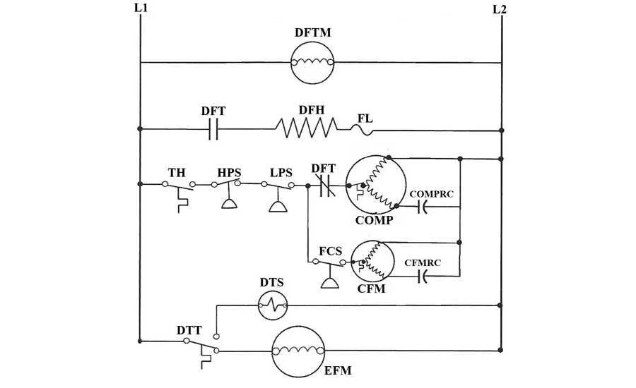
Bypassing thermal protection with jumper wires risks permanent motor damage. If the thermal overload trips, locate airflow obstructions or signs of motor overheating rather than forcing operation.
Neutral misrouting in junction boxes results in non-responsive control panels. Ensure the return path completes through the designated terminal block rather than floating ground connections.
Improper grounding of metallic enclosures creates safety hazards. Use green screws or dedicated lugs to secure ground leads directly to the chassis with ring terminals.
Timer modules installed without isolation relays may fail prematurely. Inductive loads require relay buffering to protect low-voltage electronics from back-EMF surges.