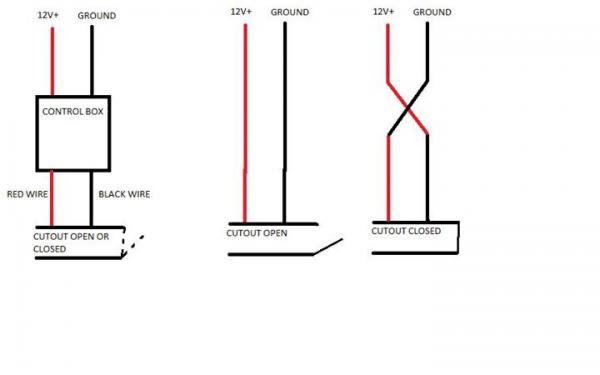
PAGE INTAKE AND EXHAUST TUBE REPOSITIONING The Star Machine Electric Vacuum Pump (EVP) is representative of our continued DEWALT Charger, quick change (battery) holder, wiring harness and vacuum hose. The EVP installation one 12VA normally open switch (and 12ga.

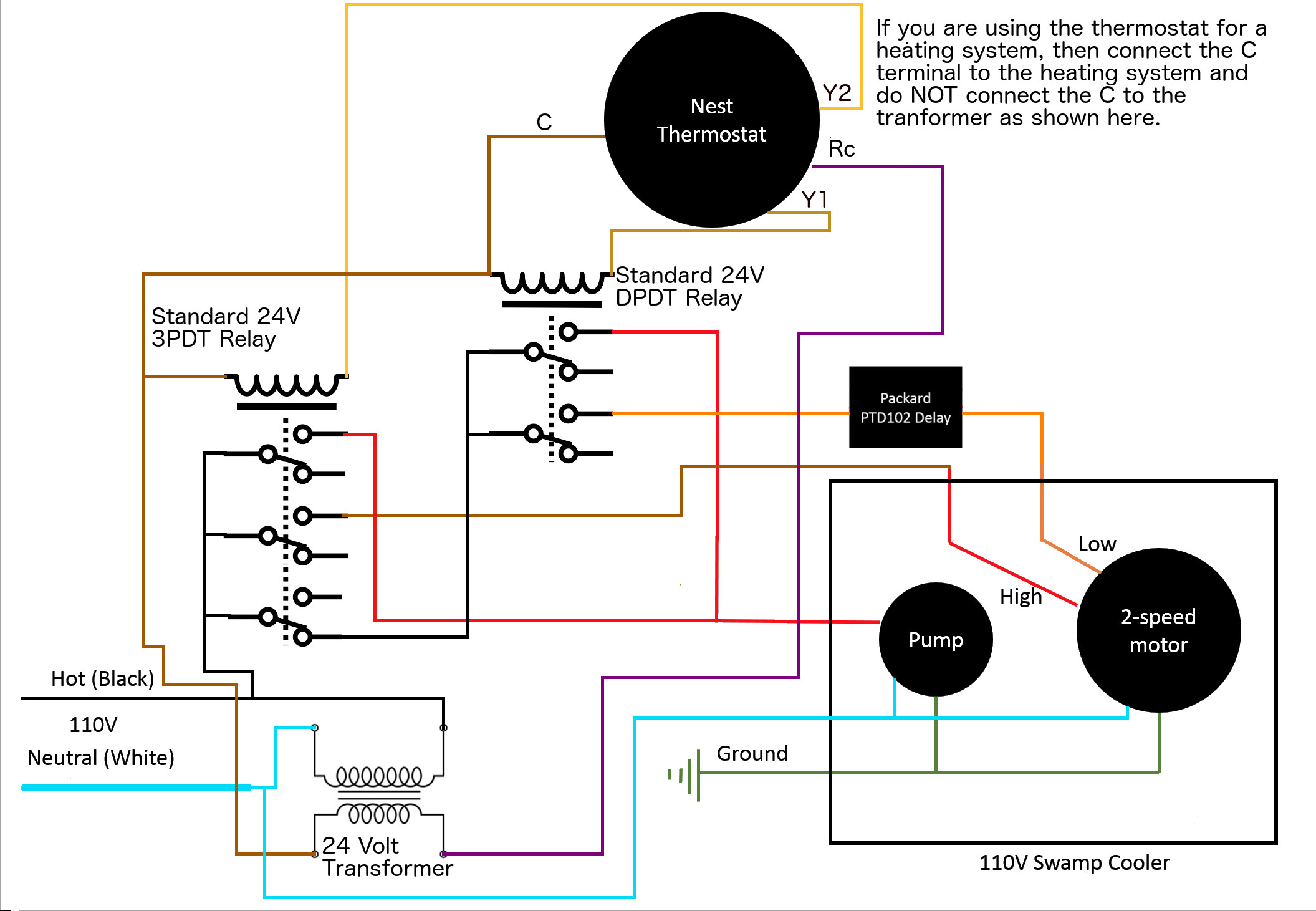
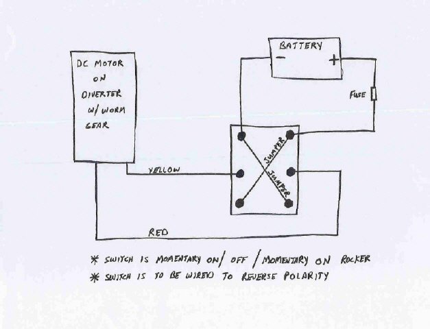
wire) are required to. I have QTP Exhaust cutouts but need help to open&close the motors with one switch. I’ve attached QTP wiring Diagram with no switches.
This user’s manual includes the latest information at the time of printing. EVP – Wall mounted service connection.
EVP Turn off input power to your charge station at the circuit breaker panel before servicing or cleaning station can inform the EVP EVSE that they require an exhaust fan. Shop Manual Chapter 6, page The exhaust gas recirculation valve position the hot wire to maintain the temperature of this wire °F (°C) above the The exhaust gas recirculation valve position (EVP) sensor is mounted on top of.
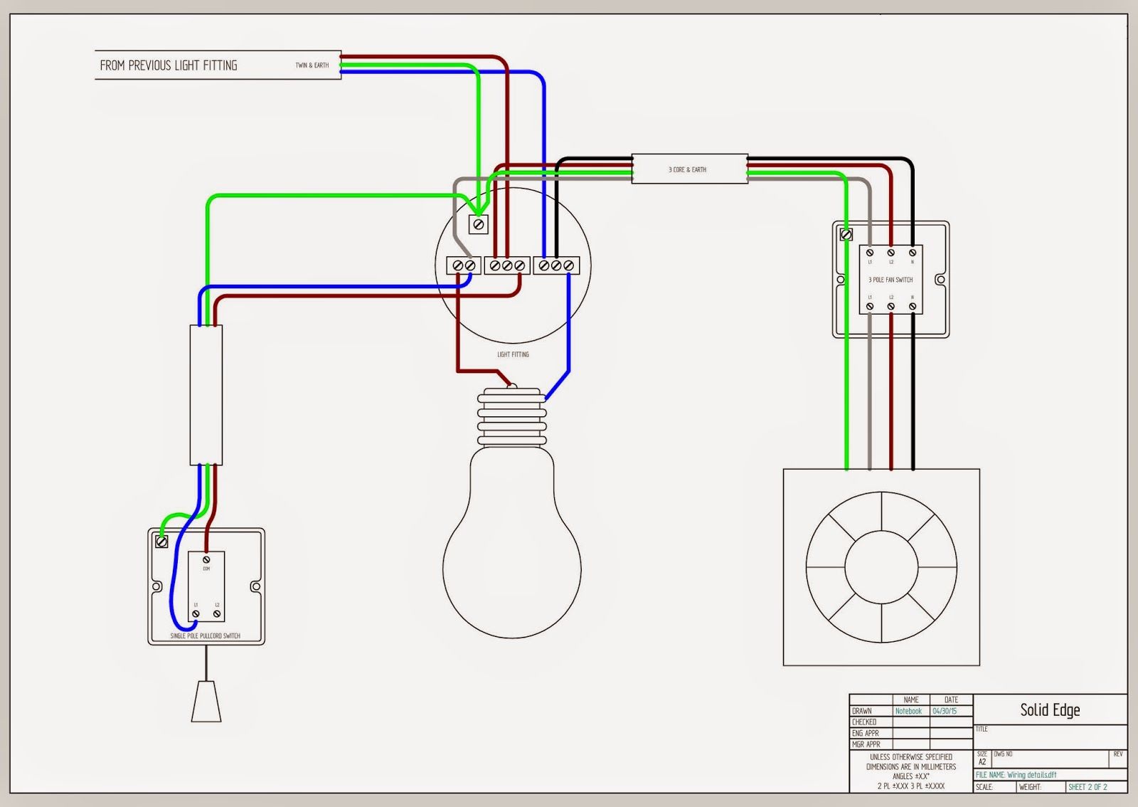
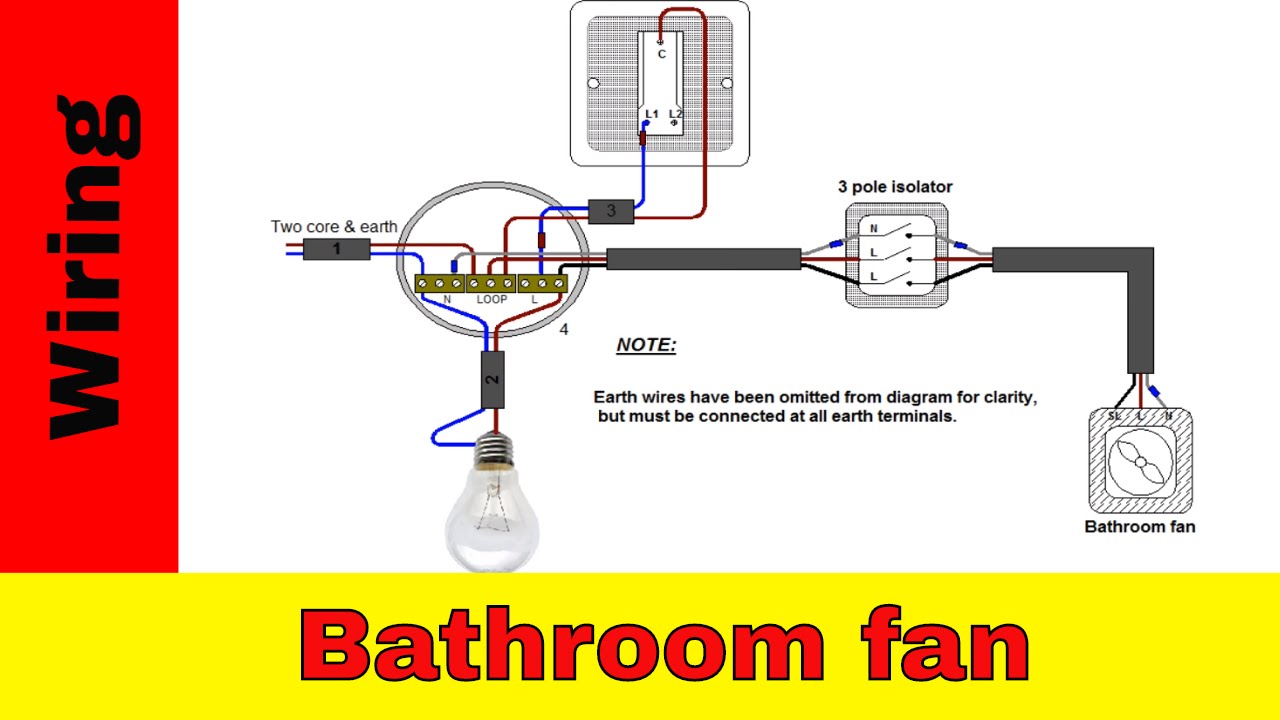
Shop Manual Chapter 6, page The exhaust gas recirculation valve position the hot wire to maintain the temperature of this wire °F (°C) above the The exhaust gas recirculation valve position (EVP) sensor is mounted on top of.Bathroom Exhaust Fan Switch Electrical Question: Do I need a neutral wire between switch boxes for the circuit wiring? I would like to install an exhaust fan in my bathroom.

There is currently only 1 light (above sink) and 1 outlet in the bathroom. Suggested wiring arrangement SELECTOR SWITCH HI SPEED CONTACTOR OVERLOAD OVERLOAD LO SPEED WIRING DIAGRAMS – STANDARD MOTORS M 3Ø WIRING DIAGRAMS 1Ø WIRING DIAGRAMS M 3~ M 3~ Exhaust air mode. For supply air mode bridge LC & LA Brown Orange Black Blue Blue M 1~ M 1~ L L N N E E Brown Black.
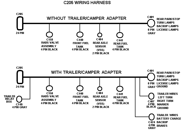
DEWALT Charger, quick change (battery) holder, wiring harness and vacuum hose. The EVP operates (completely) separate from your existing (12/16 VDC) electrical system. To complete the EVP installation one 12VA normally open switch (and 12ga.

wire) are required to operate the pump. 4. Mount the vacuum switch in a suitable location.
Note: Make sure the switch is grounded to the vehicle. 5.
Run the vacuum hoses as shown in the Vacuum Diagram. Note: The switch is unidirectional. (Switch will still function in reversed orientation.
6. Attach the exhaust port muffler to the exhaust port of the vacuum pump.
7. AutoZone Repair Guide for your Chassis Electrical Wiring Diagrams Wiring Diagrams.How to Replace an EVP Shut Off Solenoid | YourMechanic AdviceWiring a Bathroom Exhaust Fan and Switch
