Fire alarm control panel (FACP).
Fire alarm control panel design resources and block diagram Lead-acid battery charging with seamless power switchover; Multiple communication protocols on wired (Ethernet, RS, RS, USB) and . Fire alarm control panel (FACP). Fire alarm control panel design resources and block diagram Lead-acid battery charging with seamless power switchover; Multiple communication protocols on wired (Ethernet, RS, RS, USB) and .

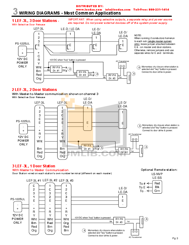
DETECTOR CIRCUIT WIRING DIAGRAM. .. The Mains supply to the FACP is fixed wiring, using Fire resisting 3-core cable (Between 1.
A of auxillary power, connection for second ANN BUS, synchronization of Central Station/Remote Station Transmitter Connection to FACP Dry Contact. FACP IQ8Control C..
. Mains connection and earth connections. ..
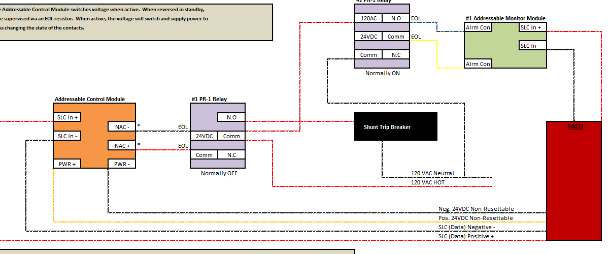
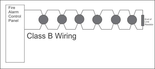
wiring illustrated in these installation instructions refer exclusively to the facilities of.B circuit, but the wiring returns to the FACP after the last initiating device. In the event of a wiring break, etc., the The ABC’s of Fire Alarm Systems – Section I Continued from page 43 trouble circuitry operates and connects line A to line D, and line B to line C, thus effectively shunting out a single break anywhere in the circuit. Jun 09, · Need old Simplex FACP wiring diagram.
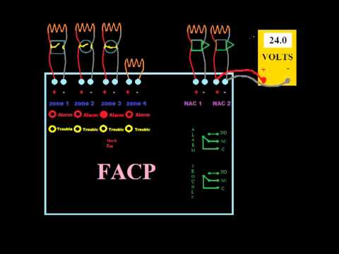
I’ve goe one to work on, but some diagrams would be helpful. All these coded gong panels were pretty close to the same, so most any old pre’s Simplex diagram will do the trick.
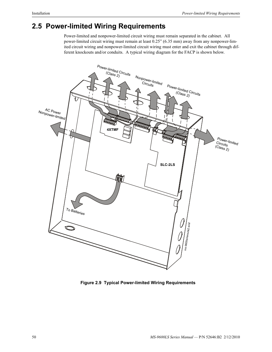
wire from safety ground (electrical distribution panel) to the green grounding screw on the FACP. The system is designed for either VAC, 60 Hz or /VAC, 50/60 Hz.
the wire. Then, slide the bare end of the wire under the appropriate clamping plate (See Figure 1), and tighten the clamping plate screw.
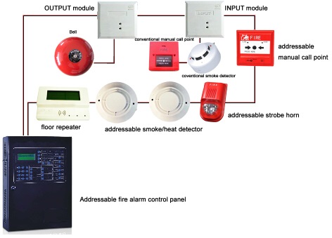
Do NOT loop the wire under the clamping plate (See Figure 2) The wiring diagram for a typical 2-wire intelligent system is shown in Figure 4. MOUNTING Mount the BS mounting plate directly to an electrical box.
Do not handle live AC wiring or work on a device to which AC power is applied. Doing so may result in severe injury of death.
FIELD WIRING 1. Wire as required per wiring diagram (Figure 2), placing the stripped wire lead under the correct terminal plate.
Extra wire lead should be clipped and terminated with a wire nut to avoid shorting to housing.FAQ – Questions About Fire Alarm Systems – Current Technologies Ltd.Fire alarm control panel – Wikipedia