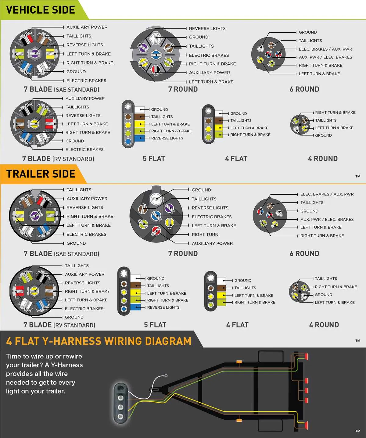
If you’re looking to set up a 6-pin connection system for your towing needs, start by identifying the correct pinout configuration. Each pin serves a specific purpose, such as powering the lights, brakes, or providing signals to the towing vehicle. Accurate placement and proper wiring are critical to ensuring safe and reliable performance.
Pin 1 is typically reserved for the ground connection. This ensures that all electrical components have a proper return path for current. Always check the grounding system for any signs of corrosion or loose connections, as this can cause electrical failures.
Pin 2 is commonly used for the left turn signal. This wire should be linked directly to the signal light on your trailer. It’s essential to test the continuity to avoid any issues with blinkers not functioning correctly.
Pin 3 is for the right turn signal, similar to Pin 2. Ensure this wire is correctly routed to the corresponding right-side signal light. Any misconnection here can result in hazards when turning or changing lanes.
Pin 4 handles the brake lights. It’s vital to connect this pin to the brake system to alert others of your braking action. Verify the voltage to ensure the system is working efficiently.
Pin 5 is typically used for reverse lights, aiding in visibility when backing up. This is especially important when maneuvering in tight spaces. Check for proper light function and troubleshoot if reverse lights don’t activate.
Pin 6 is often used for auxiliary power or electric brakes. Depending on your system, you may need to adjust the voltage or current to match the requirements of your specific towing setup. Make sure all connections are secure and properly fused.
By following this structured approach and verifying each pin’s connection, you can ensure your setup is both efficient and safe. Always perform a final test on the entire system before use, checking for proper operation of each component.
6-Wire Connection Setup for Towing Equipment
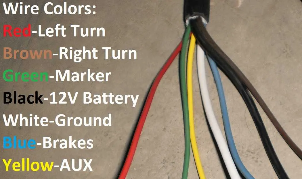
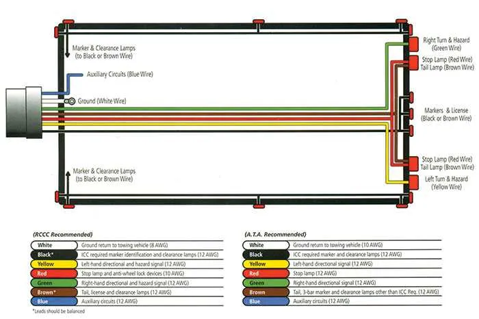
For a 6-pin connection system, the color-coded system is crucial to ensure proper installation and function. Typically, the wiring should follow the standard pattern to avoid confusion and malfunctions. The six wires serve distinct purposes, and knowing their corresponding functions is vital for safety and performance.
1. White: Ground. This wire must be securely connected to the towing vehicle’s chassis or any other metal part with a reliable ground connection.
2. Brown: Right Turn/Brake. This wire is responsible for signaling the right turn and brake lights. Make sure it runs from the vehicle’s right-side signal to the trailer lighting system.
3. Green: Left Turn/Brake. Similarly, this wire connects the left turn signal and brake lights from the towing vehicle to the trailer setup.
4. Yellow: Running Lights. This is used for the vehicle’s running lights, ensuring that the lights on the towed unit are on during driving.
5. Blue: Electric Brakes. The blue wire handles the activation of electric brake systems for controlled stopping of the trailer during towing. It should be routed from the brake controller in the towing vehicle to the trailer’s brake system.
6. Red: Auxiliary Power. This wire provides constant 12V power to accessories or auxiliary systems on the trailer, such as a battery charger or breakaway switch.
When setting up, double-check that each wire is firmly connected to its correct terminal. A poorly connected system can lead to malfunctioning lights or brakes, posing a safety risk on the road.
How to Identify Wires in a 6-Pin Connector

To identify the wires in a 6-pin connector, follow these steps carefully:
- Start by locating the common ground pin, usually the white wire. This pin is essential for completing circuits and is typically located at the bottom or center of the connector.
- Next, identify the left turn signal wire, which is often green. This wire will control the left side indicators.
- The right turn signal is usually represented by a yellow wire. It connects to the right side signal lights.
- The brake lights wire is commonly red. This wire is responsible for activating the brake light circuit.
- The reverse light wire, often blue, powers the reverse lights when the vehicle is shifted into reverse.
- Finally, the auxiliary power wire is typically black or brown. It provides 12V power for accessories like electric brakes or other additional functions.
Ensure all connections are secure and insulated to avoid any electrical issues. Testing with a multimeter can help confirm the functionality of each pin before use.
Step-by-Step Guide to Installing a 6-Wire System
1. Gather Necessary Tools and Materials: Before beginning, ensure you have a suitable power source, connectors, crimping tool, heat shrink tubing, wire cutters, and a multimeter for checking the connections. Additionally, use high-quality, weather-resistant cables to ensure longevity.
2. Plan the Installation Path: Identify where each wire will be routed along the vehicle and cargo unit. Keep wires away from sharp edges, hot surfaces, and moving parts. Use cable ties to secure the wires along the planned route.
3. Prepare the Connector: The 6-wire connector should match the appropriate pinout for your specific vehicle and equipment. Use a pin removal tool to position each wire into its correct slot, ensuring a secure connection without any risk of shorts.
4. Attach the Wires to the Pins: Insert each wire into the designated pins, following the pinout chart. The usual configuration includes a ground wire, left and right turn signals, brake lights, running lights, and auxiliary power. Use a crimping tool to secure the wires firmly to the connectors.
5. Check for Proper Grounding: The grounding connection is crucial for system functionality. Connect the ground wire securely to the vehicle’s chassis, ensuring there is no paint or rust interrupting the connection.
6. Test Each Function: Before finalizing the installation, test each function (signals, brakes, and lights) using a multimeter or a dedicated test device. This will confirm all connections are correct and functional.
7. Insulate and Secure: Once you’ve confirmed the wiring is functional, insulate each connection with heat shrink tubing to protect against corrosion and weather. Secure all wires to prevent movement that could cause wear and tear over time.
8. Final Checks: Perform a last check to ensure that all connectors are tight and there is no slack or excessive strain on the wires. Re-check for any potential short circuits or exposed wires.
9. Test Again: After securing all components, conduct a final test to ensure everything operates as expected during real-world use.
Troubleshooting Common Issues with 6-Wire Electrical Connections

If the brake lights or turn signals aren’t working, check the ground connection first. A loose or corroded ground can cause intermittent or no signal. Ensure the ground wire is securely attached to a clean, metal surface.
For dim or flickering lights, inspect the power feed wires for any breaks, corrosion, or loose connections. Tighten any loose connectors and replace damaged sections of the wire. Pay attention to the quality of the connectors used, as poor-quality ones can lead to unstable performance.
Check the continuity of each individual circuit with a multimeter to ensure there’s no break or short along the wire path. If one of the circuits isn’t delivering power, locate the fuse related to that specific line and replace it if necessary.
If you’re experiencing problems with the brake or reverse lights, ensure the correct color-coded wires are connected to the corresponding terminals. Miswiring can lead to malfunctioning lights or a non-functional brake system.
For issues with the 12V power supply, ensure the power wire is connected to a proper source. Confirm that your power feed wire is thick enough to handle the load, as under-sized wires can cause voltage drops and power issues.
Finally, when troubleshooting intermittent issues, check the connections for corrosion or moisture. These conditions can cause unstable performance and even complete failure of the electrical system over time.