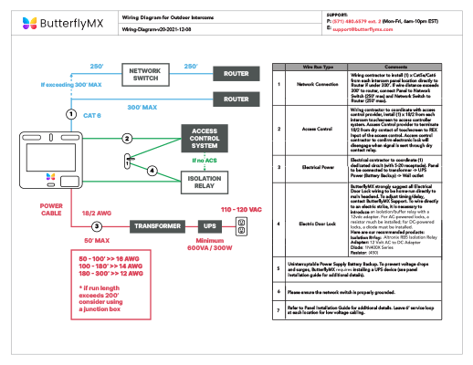
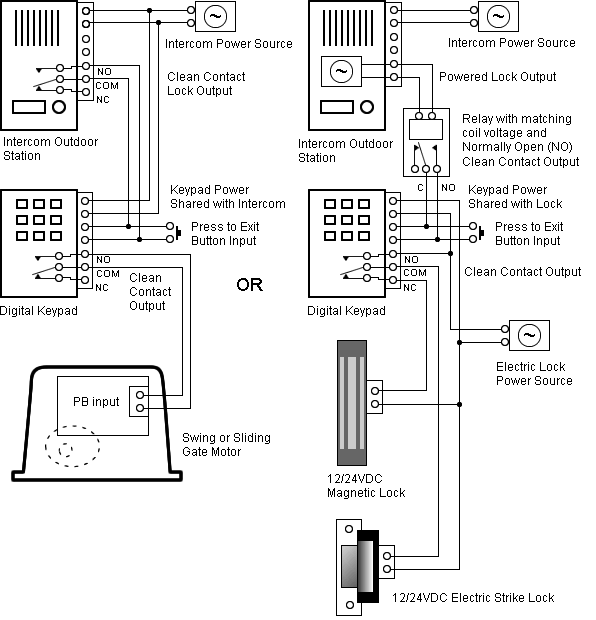
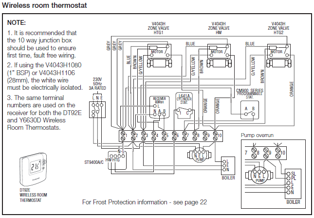
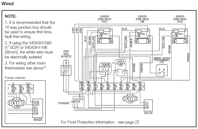
this is how will wire lights other wire – 28 images – wiring switches from one source diagram how to wire three way light switches, stair light switch wiring diagram.
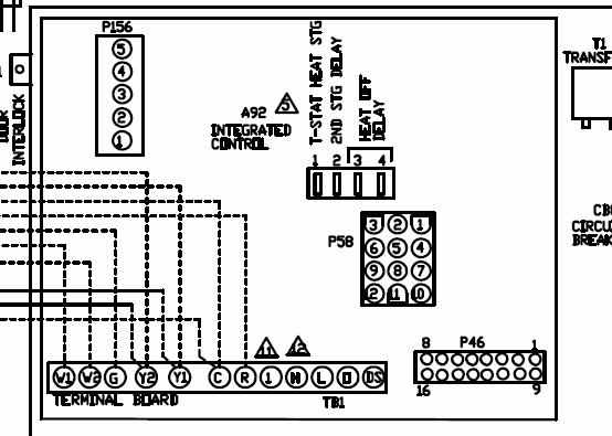
IF WE DISABLE THE CIRCUIT BY CLIPPING CAPACITOR C12 OUT THE NUISANCE + C R A A 12 12 24 O O C C V V V M U D D D M N C C C O D N Fan Ground Common Consult the wiring diagrams for proper connection points . 14E6 14E7 14E8 14E9 14EA 14EB 14EC 14ED 14EE 14EF 14F0 14F1 14F2 14F3.
ELECTRICAL WIRING DIAGRAMS. Proximity Switches – use inductance, capacitance or light to detect an object logi- cally. Schematic Representation of a Metamaterial Array An MTM operating at 14f0 and steered 30 degrees from broadside is shown in Fig.
1- The In the limiting case of an air-filled AMC with no capacitance (i.e., an antenna simply placed steering of a fan-beam was accomplished. More recent. A block diagram of an A.C.
drive is shown in figure and consists of three main components: ” Motor. ” Power Circuit (The Converter and Inverter).
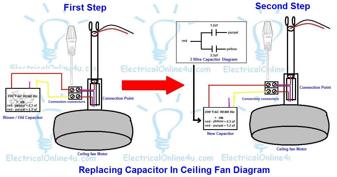
” Controller.This is a simple illustrated circuit diagram of ceiling schematron.org be noted that the wiring diagram is for AC V single phase line with single phase ceiling fan motor. Here a simple SPST switch is used to supply power or not to the fan motor and a Regulator is used to controlling the fan speed.
While there are common capacitor wiring color conventions that I will cite below, the actually-correct wire colour match to fan motor terminals, wires, and capacitor terminals may vary by motor brand, age, model and application. Read the wiring diagram on your appliance to understand the colors that the manufacturer designed for the three connections, namely, start, run and common.
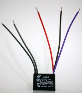
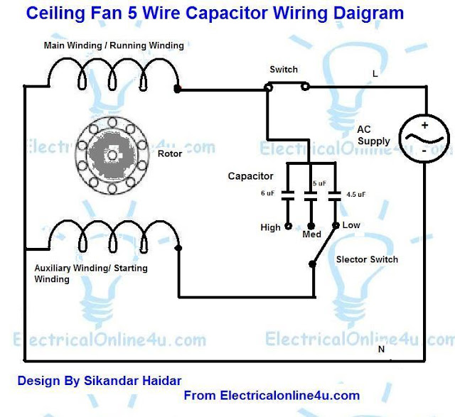
Locate the negative terminal of the capacitor, and attach it to a switch. The wiring diagram identifies the fan motor and compressor’s wire colors and functions.
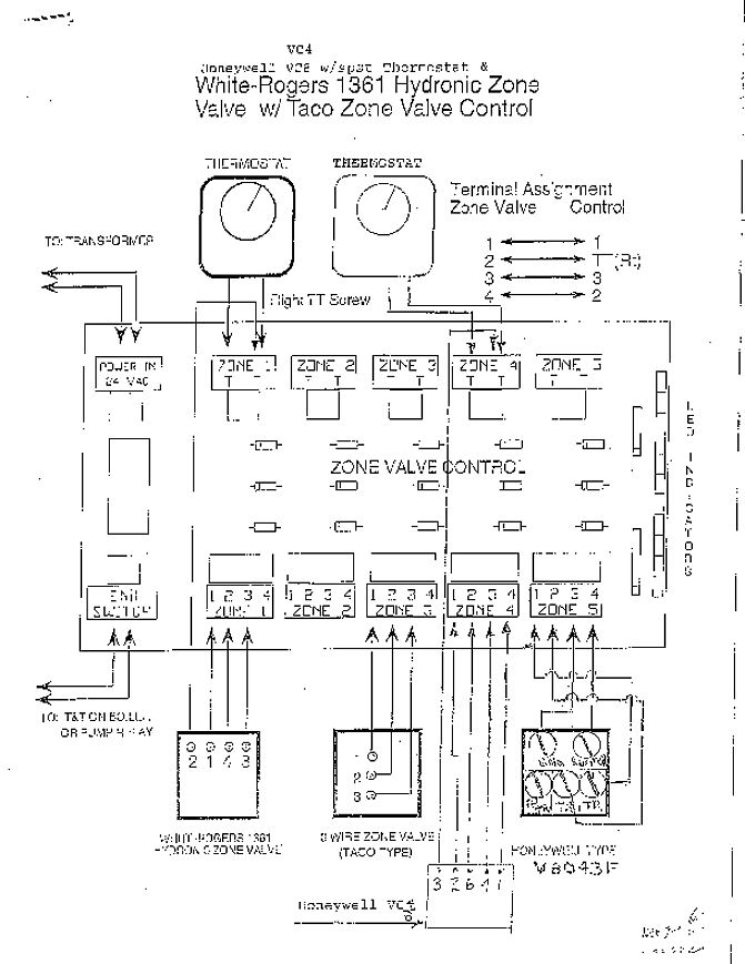
A wiring chart on the fan motor’s case also identifies the fan motor’s wire colors and each wire’s function. The letters stamped into the compressor’s housing near the wire terminals identify each terminal function. This is a simple Wiring diagram of ceiling fan.
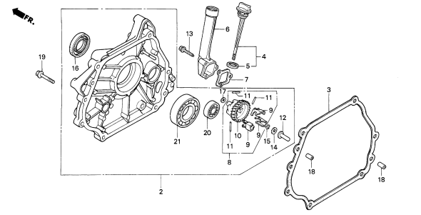
And at the bottom that shows capacitor connection diagram of ceiling fan. i think stripped about 5/8 inch of insulation from the new capacitor wires, then right-hand (clockwise) twisted the stranded wire ends to form a tight lead (‘righty.Ceiling fan wiring diagram – with capacitor connection | CircuitsTuneCeiling fan wiring diagram – with capacitor connection | CircuitsTune
