FANUC I/O Unit-MODEL B. I/O Unit-B.
Abbreviations of manufacturer names used herein. This manual uses the following abbreviations for manufacturers of. Fanuc R-J Controller Series Electrical Connection and Maintenance Manual FANUC Robotics SYSTEM R-J3 Controller Si Series Mechanical Unit .
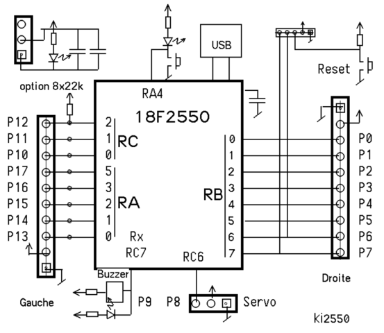
Diagrams. Find complete schematics of the controller circuitry.
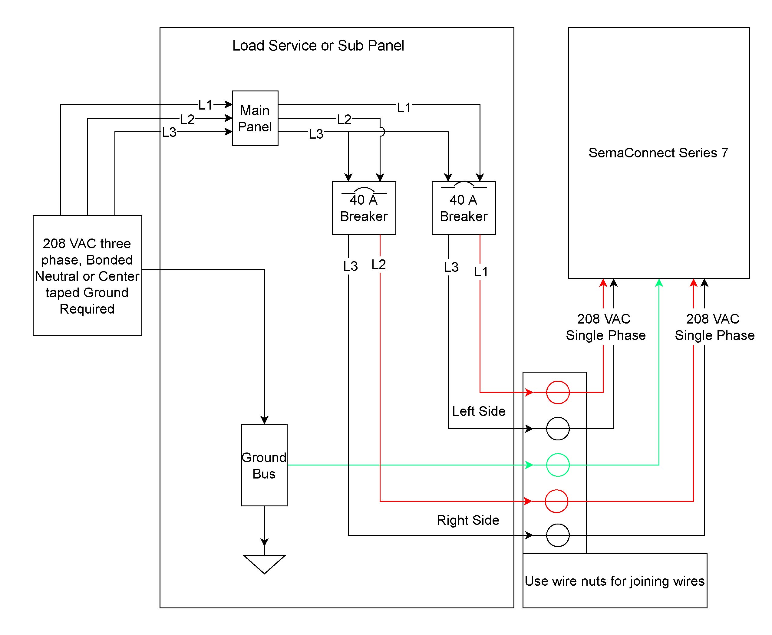
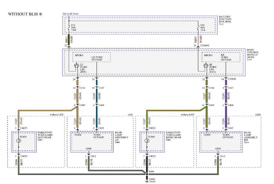
Fanuc Cable Wiring Diagrams
Chapter 13, Prints. FANUC has a wide range of robot types and models available for various Replacing manual operations with robots Matching controller/Input power capacity.

Before using the Robot, be sure to read the “FANUC Robot Safety Manual (B- EN)” This manual can be used with controllers labeled RiA or R-J3iC. The Pick-it processor has to be connected to the Fanuc controller using an Ethernet cable. This Ethernet cable should be.This wonderful image selections about fanuc cable wiring diagrams is available to download.

We collect this wonderful photo from internet and choose one of the best for you. fanuc cable wiring diagrams images and pictures selection that uploaded here was carefully selected and uploaded by author after choosing the ones that are best among the others. cbse guide fanuc maintenance manual – free ebooks download study fanuc rj3ib robot maintenance manual physical ge_ fanuc_ wiring_diagram by tuangov – schematron.org kia owners manual fanuc rj3i controller manual – ebooks free hobet study fanuc ria e-stop wiring diagram – schematron.org – .
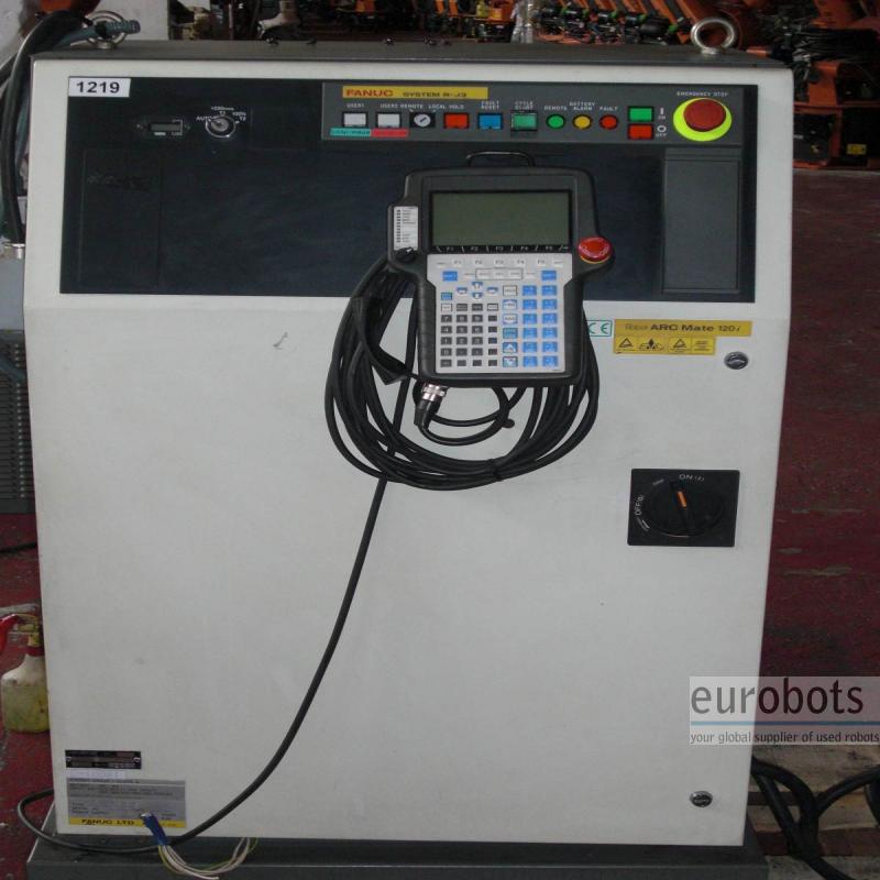
FANUC Robotics SYSTEM R-J2 Controller HandlingTool Setup and Operations Manual Version MARO2HTE REV. B This publication contains proprietary information of FANUC Robotics North America, Inc. furnished for customer use only.
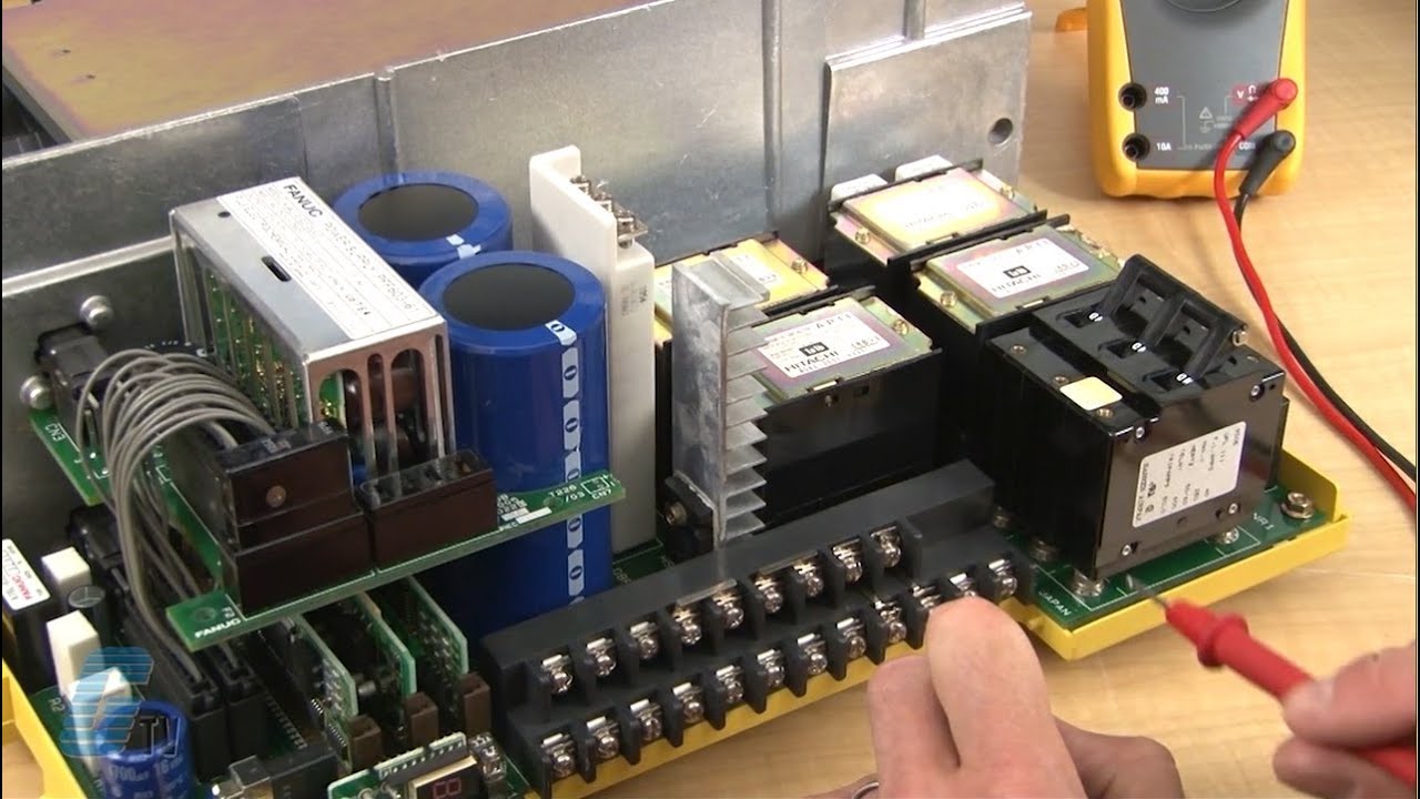
No other uses are authorized without the express written permission of FANUC Robotics North America, Inc. Thanks mvaughan.
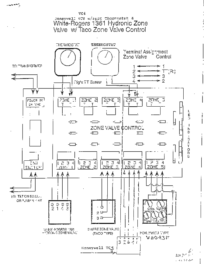
I believe my question was worded wrong. I needed a diagram of the safety signals the controller uses. I ended up finding a diagram in a Rj3-iB maintenance manual.
The robot controller is designed to be connected to an external EMERGENCY STOP button. With this connection, the controller stops the robot operation when the external EMERGENCY STOP button is pressed.
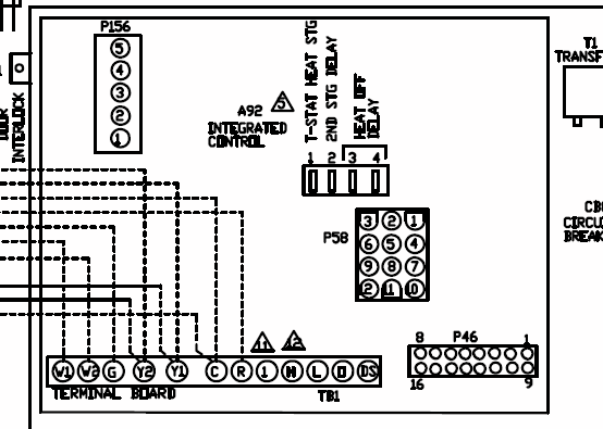
See the diagram below for connection. External EMERGENCY STOP button Panel board Note) Connect between EMGIN1 and EMGIN 2.fanuc RJ3 controller manualFanuc Cable Wiring Diagrams.
Wiring. Wiring Diagram Images
