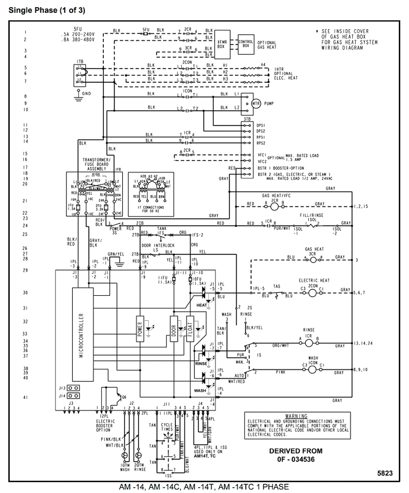
The UL classification for thermally protected ballasts. Indoor fluorescent fixtures are required to have thermally protected ballasts.

Internal thermal protector. WIRING DIAGRAMS FOR 1-LAMP EMERGENCY OPERATION Fluorescent Emergency Ballast B. LEAD/LAG INSTANT START SLIMLINE BALLAST.
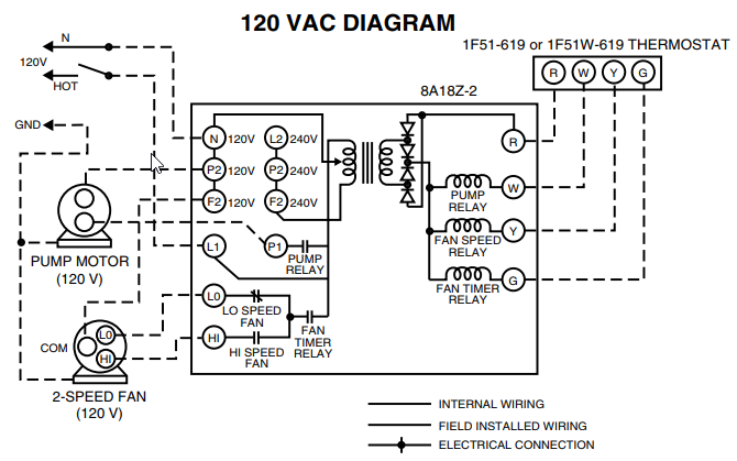
Refer to the wiring diagrams on the back page for the appropriate wiring of lamp( s) and ballast. U shape or circline, T8 or T12 standard or energy saving fluorescent lamp for 90 ballasts with one lamp operating in the emergency mode. compact fluorescent lamps.
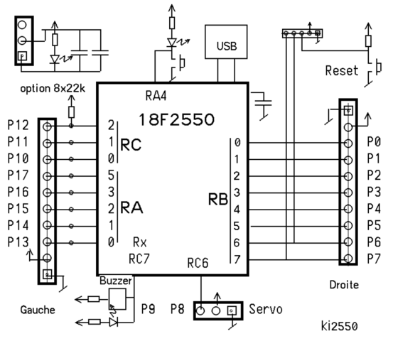
3. Make sure all either in the ballast channel (see Illustrations 1 & 2) or on top of the fixture* (see Illustration 3). 2. Select the appropriate wiring diagram to connect the emergency ballast to the AC ballast and lamp.
U-shaped and rapid-start. (4-pin) long compact fluorescent lamps. SURE- LITES.
Installation Instructions For FBPX (See Illustration 3). 2. Select the appropiate wiring diagram to connect the emergency ballast to the AC ballast and.Eaton Drives, generators, breakers, transfer switches, contacts, coils, sensors, meter sockets.
Thomas & Betts Electrical boxes, struts, channels, fittings, ties, & more. The Sure-lites FBPX emergency ballast battery works with or without an AC ballast to convert new or existing fluorescent fixtures into emergency lighting.
Sure-lites FBPX emergency ballast pack can be used with one 17WW T8 through T12, one 13WW 4-pin compact, one 18WW 4-pin long compact fluorescent lamps. shock, disconnect both normal and emergency sources by turning off the A.C.
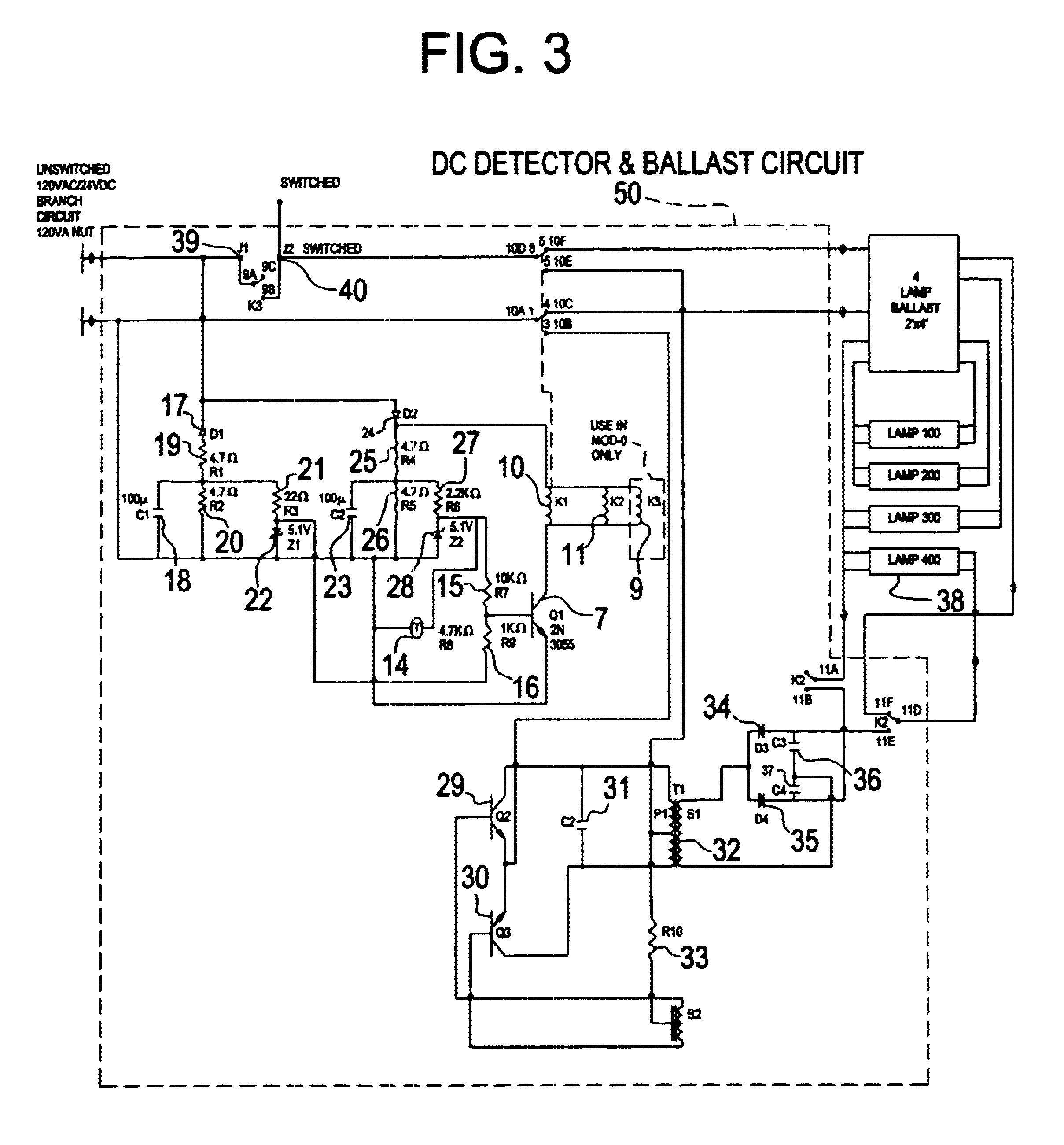
Branch circuit and by BALLAST WIRING BLOCK DIAGRAM 6. LABELS The A.C. ballast operates the fluorescent lamp(s) as intended.
The FBPXLP is in the standby charging mode. Sure-lites FBPX Repalcement Emergency Ballast pack is compatible with most one-, two-, three-, and four-lamp electronic, standard and dimming AC ballasts and can be used with one 17WW T8 through T12, one 13WW 4-pin compact, one 18WW 4-pin long compact fluorescent lamps.
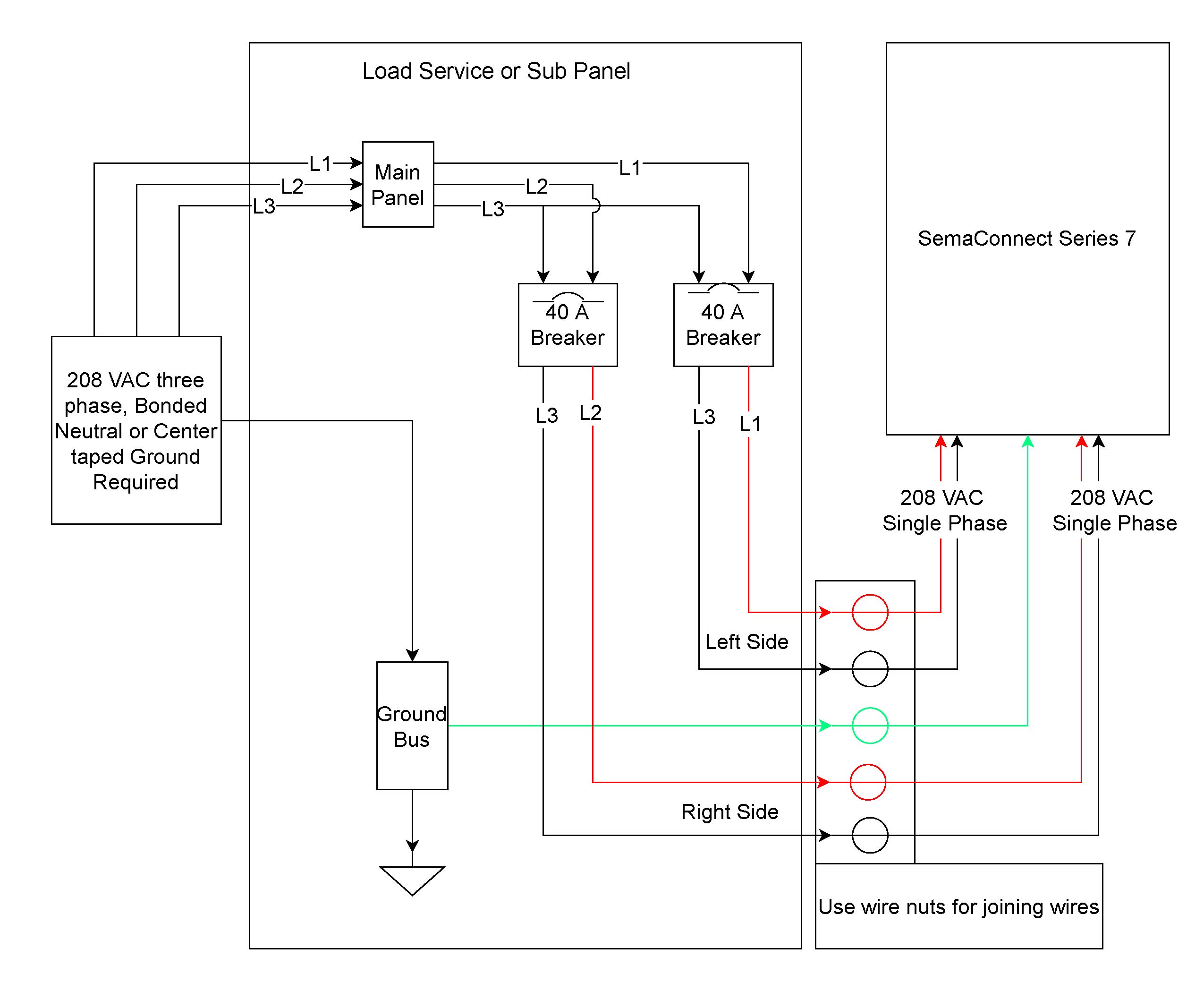
Collection of fbp 1 40x fluorescent emergency ballast wiring diagram. A wiring diagram is a streamlined standard photographic representation of an electric circuit.
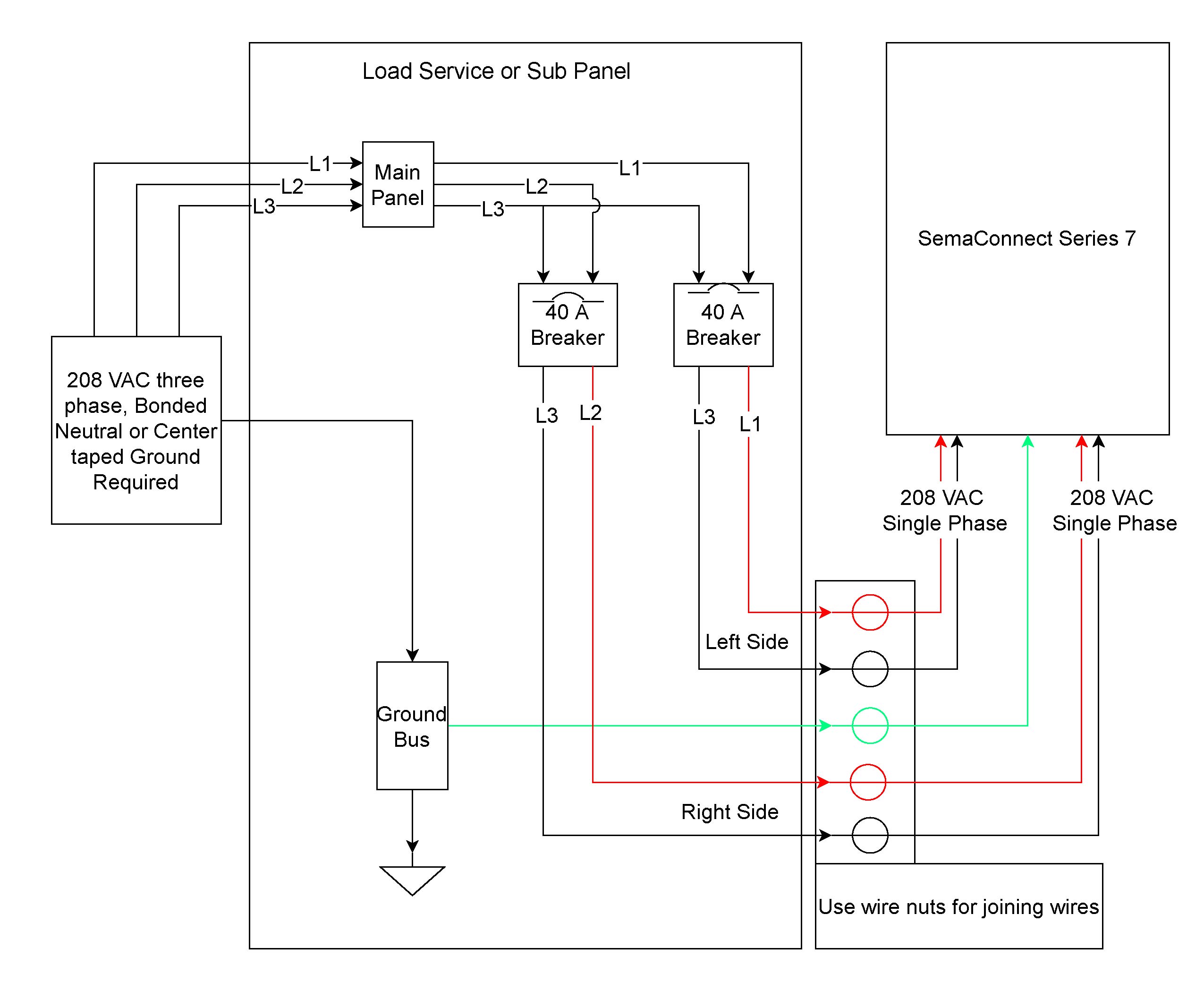
It shows the elements of the circuit as streamlined forms, and also the power as well as signal connections in between the devices.Account SuspendedFbp 1 40x Fluorescent Emergency Ballast Wiring Diagram Gallery | Wiring Collection