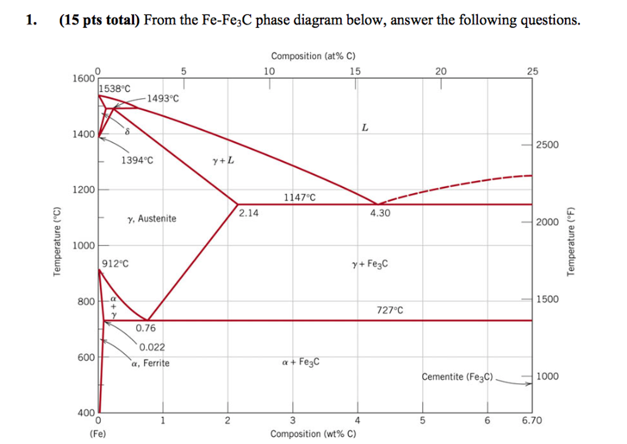
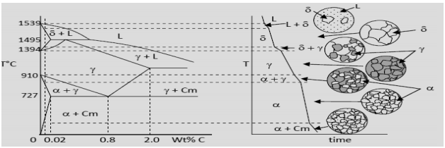
Figure 1 shows the equilibrium diagram for combinations of carbon in a solid solution of iron. The diagram shows iron and carbons combined to form Fe-Fe3C at.
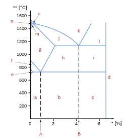
Fe-Fe3C phase diagram. Iron and Steel. Steel Microstructures.
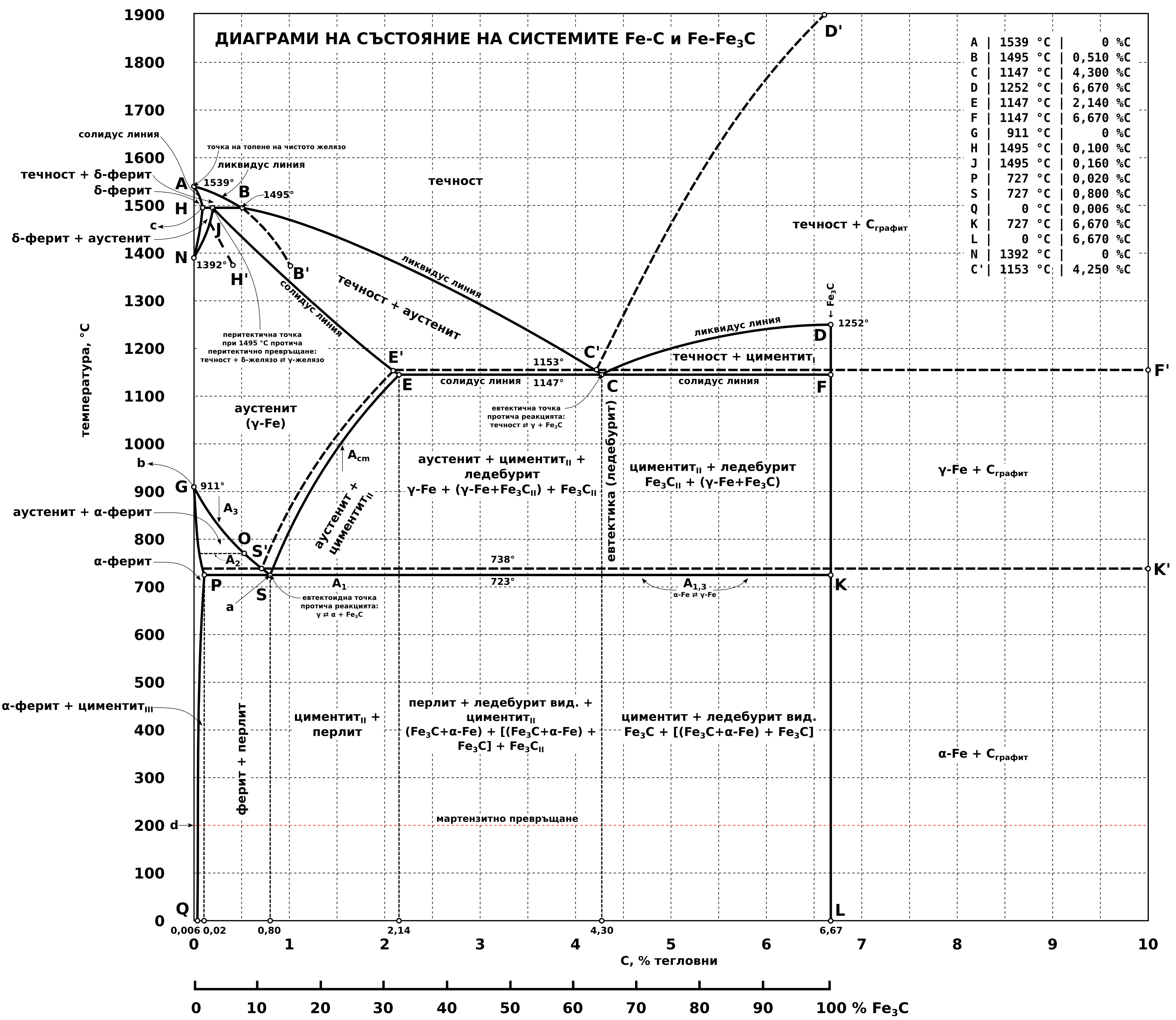
1. Phases and Microstructure.
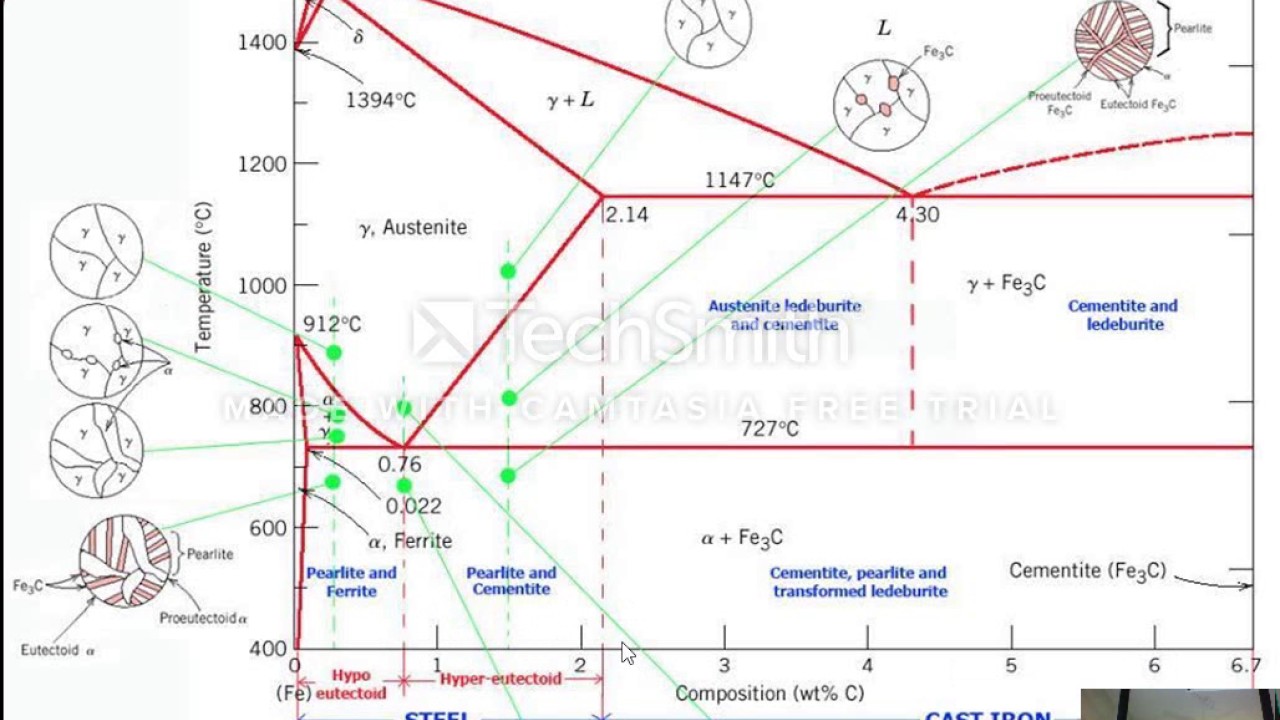
Knowledge Incubation for TEQIP IIT Kanpur. The iron-iron carbide (Fe-Fe3C) phase diagram is shown in the figure below. Austenite containing wt.% of carbon was cooled from °C to a temperature.
Iron Carbon Phase Diagram, TTT Diagram, CCT Diagram. g-austenite (FCC) Fe-C solid solution d-ferrite (BCC) Fe-C solid solution Fe3C.
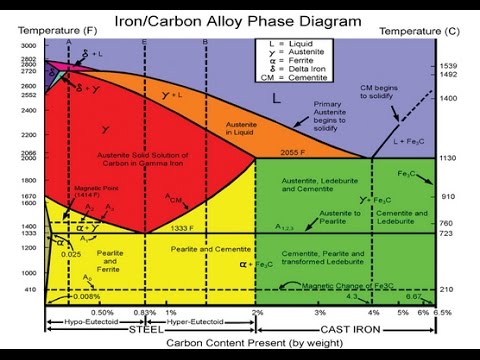
Carbon (C). The Fe-C phase diagram is a fairly complex Phases in Fe–Fe. 3 . ( – ).
Fe-C phase diagram
Fraction of proeutectoid cementite: W. Fe3C. = V / (V+X) = (C.
1.Iron–Carbon Phase Diagram • In their simplest form, steels are alloys of Iron (Fe) and Carbon (C). • The Fe-C phase diagram is a fairly complex one, but we will only consider the steel and cast iron part of the diagram, up to % Carbon.
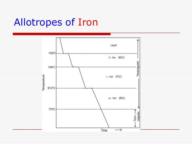
3. Fe – C Equilibrium Diagram 4.
Muddiest Point- Phase Diagrams I: Eutectic Calculations and Lever Rule
In heat treating of steels, the liquid phase is always avoided. The steel portion of the Fe-C phase diagram covers the range between 0 and wt.
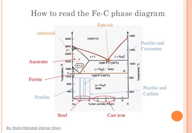
% C. The cast iron portion of the Fe-C phase diagram covers the range between and wt.
% C. Module II Diffusion in crystals Theory of Alloys Equilibrium Diagrams Iron Carbon Phase diagram TTT Diagram Heat Treatment Recovery, Recrystallisation & Grain Growth 2 3.

Allotropes of Iron 4. Fe – Fe3C Phase Diagram 5.
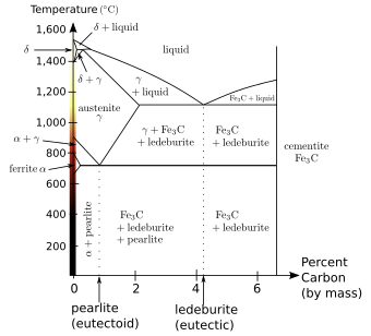
Fig 1 Iron Carbon phase diagram. The diagram shown in Fig 1 actually shows two diagrams i) the stable iron-graphite diagram (dashed lines) and the metastable Fe-Fe3C diagram. The stable condition usually takes a very long time to develop specially in the low temperature and low carbon range hence the metastable diagram is of more interest.
Minecraft Circle Diagram. Standing Rigging Diagram. 3 Position Switch Wiring Diagram. Ocean Ecosystem Food Chain Diagram.
Plano Concave Lens Ray Diagram. Chevrolet C Wiring Diagram.

Fantastic Fan Wiring Diagram. Simple Boat Wiring Diagram.
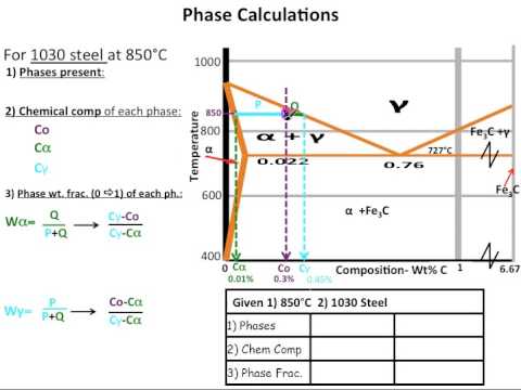
Browning Buckmark Parts Diagram. Giant Octopus Diagram. Dodge Durango Wiring Diagram.Iron-Iron Carbide Phase Diagram ExampleThe Iron-Carbon Phase Diagram | schematron.org
