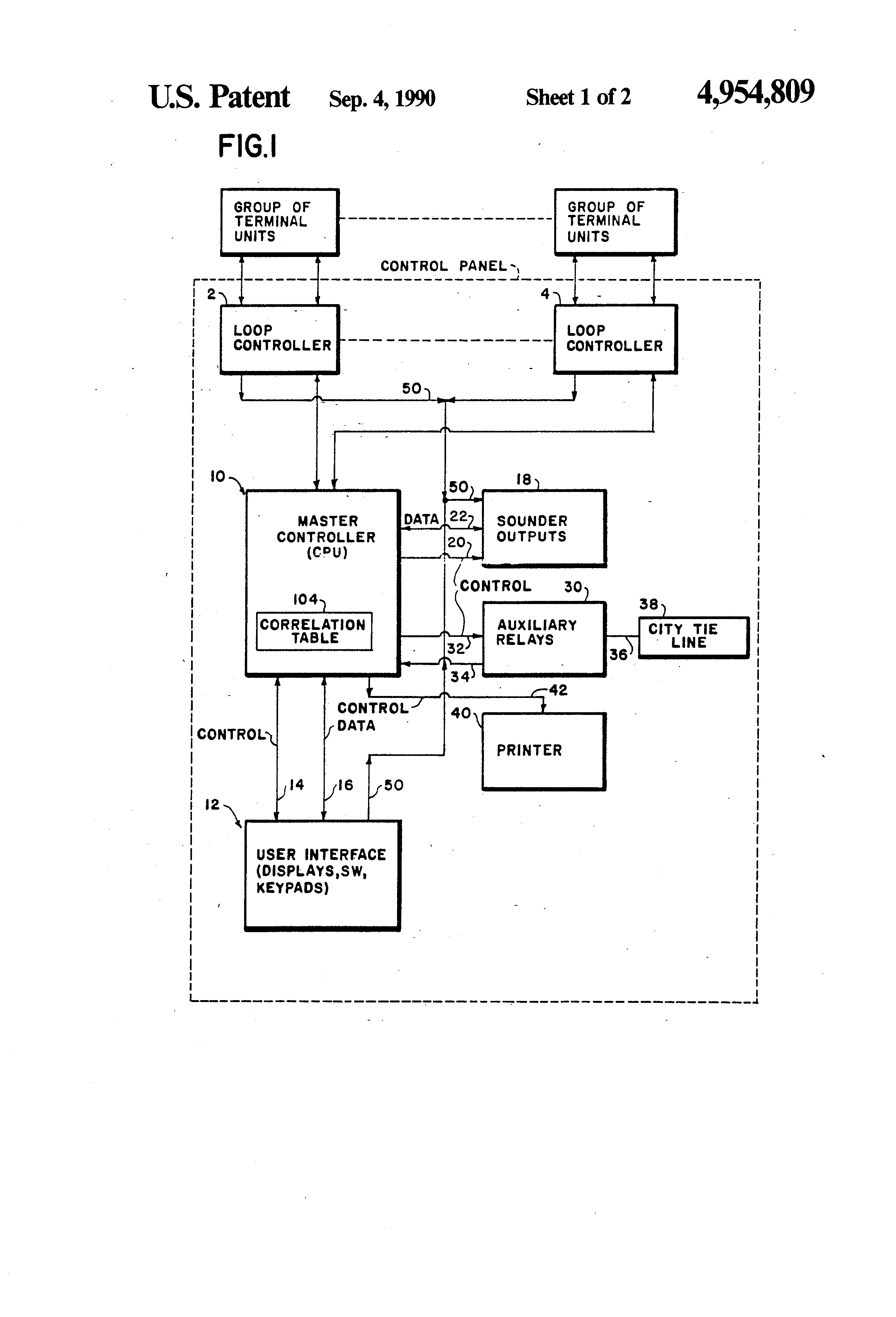
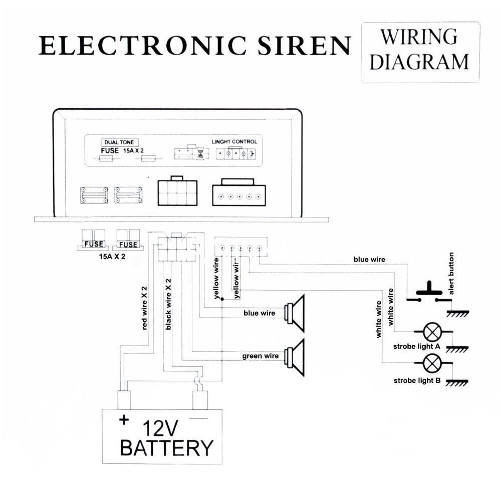
This appliance is intended for use in fire alarm systems and is to be installed . w Use only two wires to synchronize the temporal horn and strobe with the ) FOR SYNCHRONIZATION MODULE WIRING DIAGRAMS.
NOTE: WHEN USING HORN ONLY MODELS ON A FACP LISTED AS SPECIAL to a Fire Alarm Control Panel (FACP), or provide a synchronized strobe appliance when . Figure 3, the wiring diagram, is for the operation of the appliances.
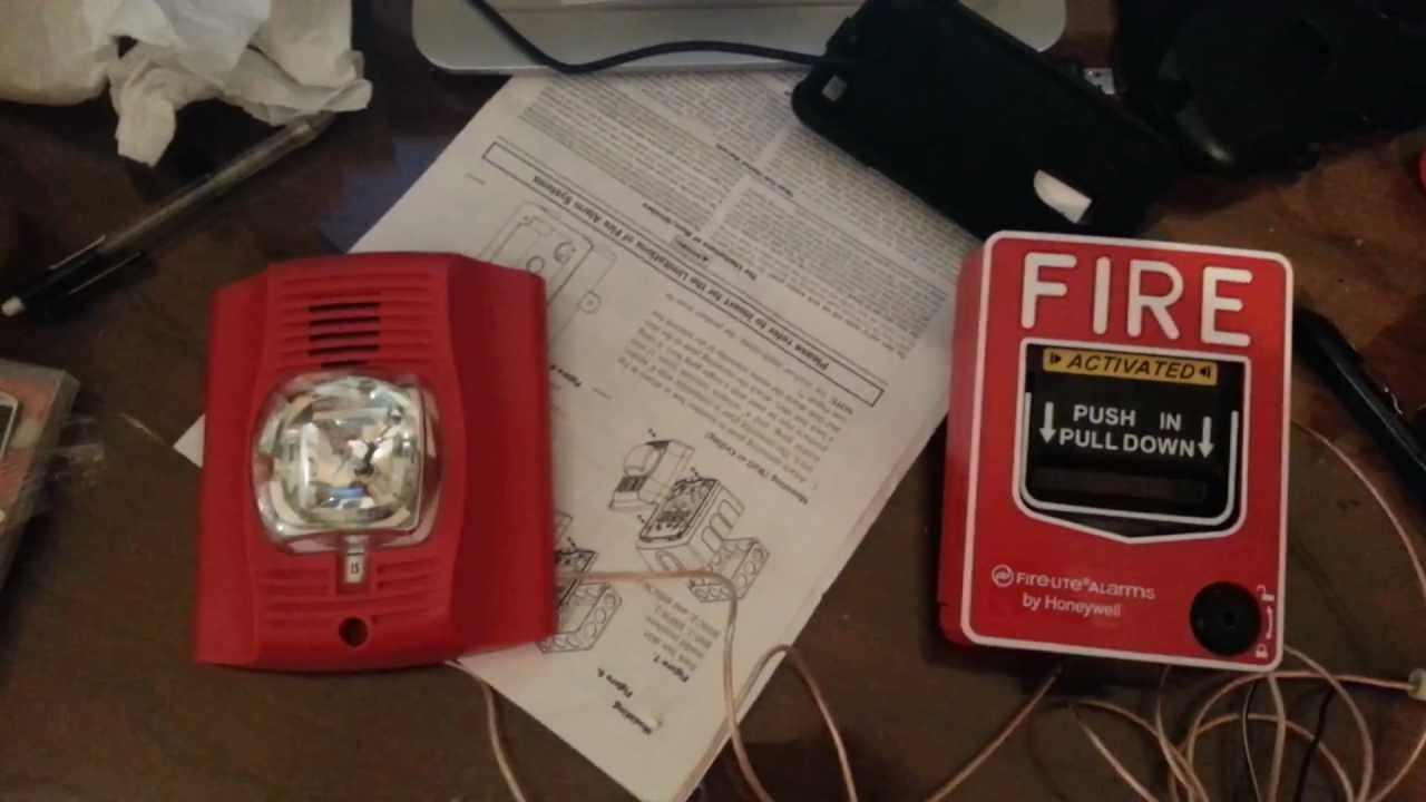
Selectable Output Strobes, Horns, and Horn/Strobes. Ohio Avenue, St. tended for systems which have separate wiring circuits for the horn and strobe.
The National Fire Alarm Code, NFPA 72, requires that all horns, used for building . designed to provide audible and visual signals for Fire Alarm.
Protection CSH24W combines a selective 2 tone horn with a colored light. Select-A-Strobe.
the strobes remain flashing, Refer to the wiring diagram Fig.1 yr dBA refer to Table 1. produce the synchronized code 3 horn and synchronized strobe upon actuation.
Fire Alarm Systems
Audible Signal Devices for Fire Alarm Systems and CAN/ULC-S for Visual Signal . Class B Wiring Diagram for the Sync Strobes (Series LLFH Hz).Fire Alarm Systems Control Panels.
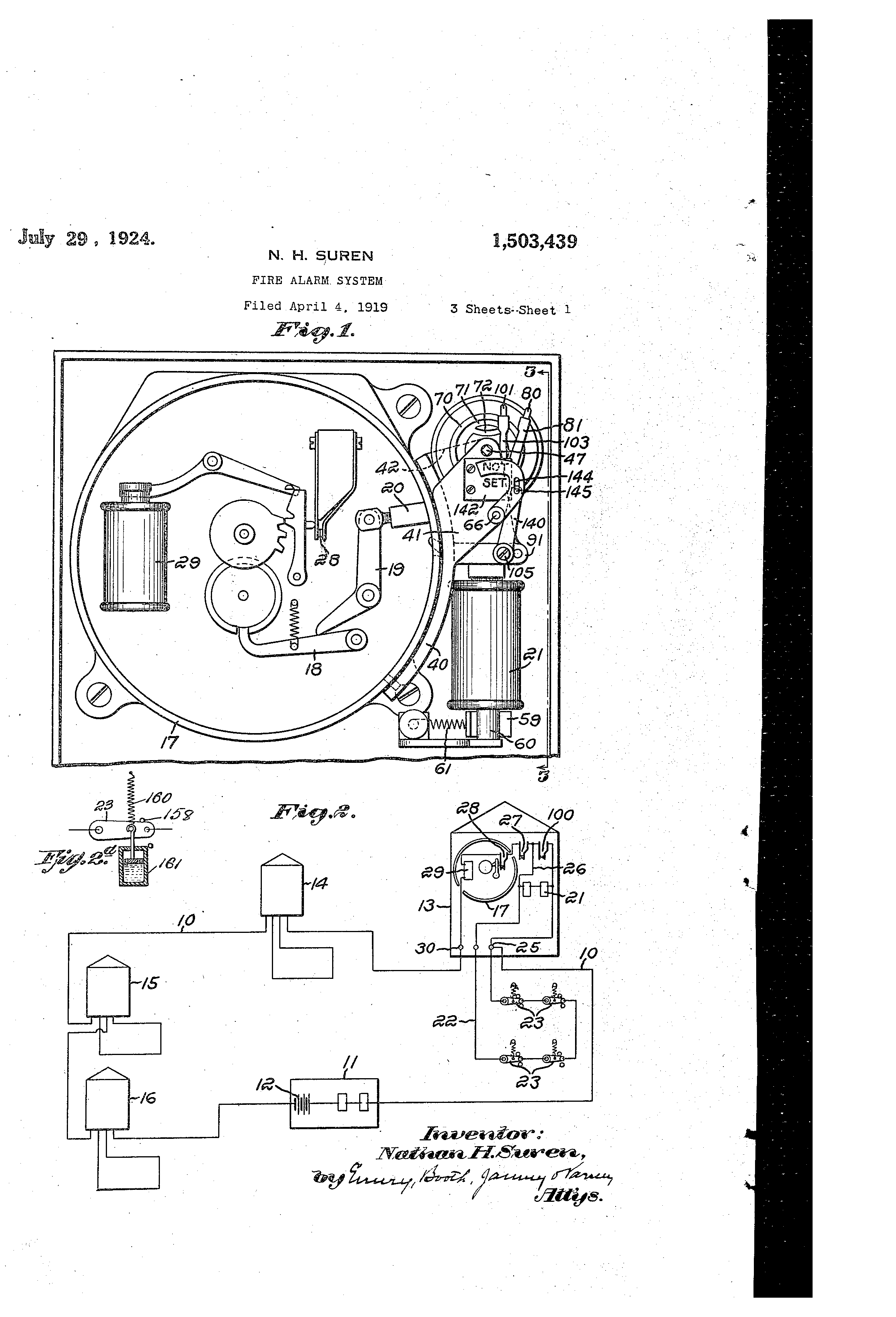
Conventional fire alarm panels and communicators; Intelligent fire alarm panels; SWIFT Smart Wireless Integrated Fire Technology for when wiring is not an option. Indicating Appliance Circuits connect the fire alarm panel to the components which alert building occupants of the fire, i.e., bells, horns, speakers, strobe lights, etc.
The following illustrations show schematics, wiring connections, riser diagram, and wire pull, for some commonly used fire alarm circuits. System Sensor Horn Strobes are rich with features guaranteed to cut installation time and maximize profits. Intended for full building notification as well as on the property ground, they produce a loud sound to notify occupants to evacuate the buildings; the strobe is intended to notify those that may have a hearing impairment.
where a single NAC controls both horn and strobe. The 4-wire products are in – tended for systems which have separate wiring circuits for the horn and strobe.
All SpectrAlert Advance products are suitable for use in synchronized systems. The System Sensor MDL3 module may be .
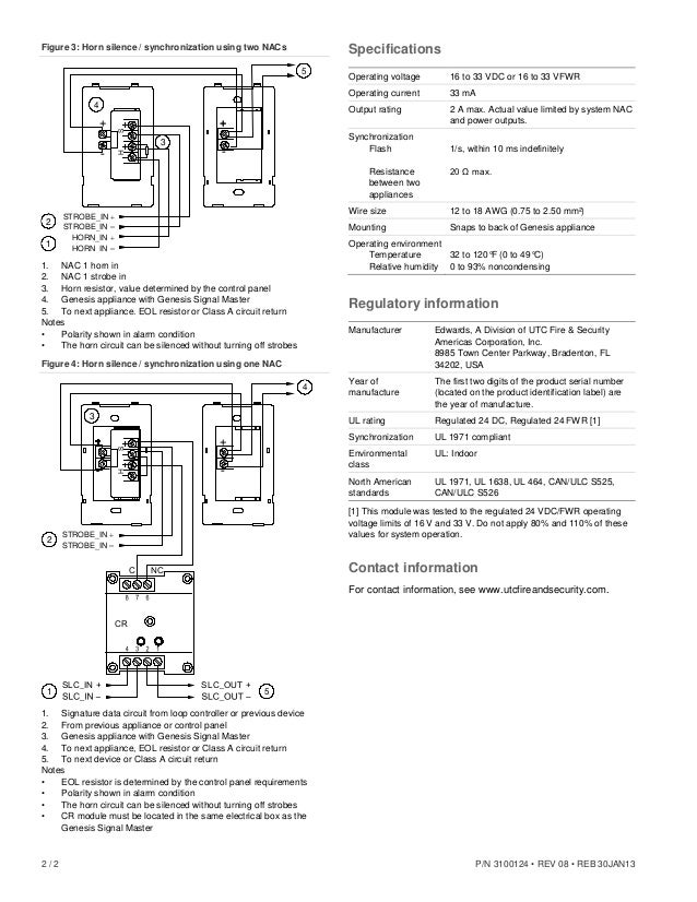
FIRE ALARM SECURITY ACCESS CONTROL CCTV Wiring diagrams provided herein are for information and reference only and Integrity: Horns, Horn-strobes: Series 54 Hazardous Location Notification Appliances 4 Diagrams are for reference only.Lightbreeze Technologies & SystemsOf Alarm Siren Circuit Diagram, Fire Alarm Horn Strobe Wiring Diagram, Fire, Free Engine