Orlov finds ethene from synthesis gas over NiPd catalysts. Fischer and Tropsch report about the preparation of Sasol II & III flow scheme.
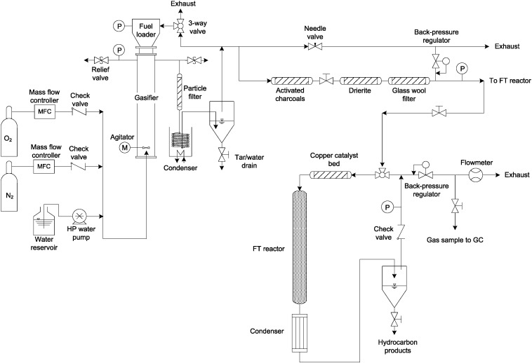
gas is then converted to liquid hydrocarbons in a two-stage, Fischer-Tropsch slurry-bed Figure 1 is a simplified block flow diagram showing the overall process. Figure 6A-1 –DWG B Process Flow Diagram – Plant Fischer-Tropsch Synthesis.
Figure 6A-1 –DWG B Process Flow. An important requirement of the reactor for the Fischer–Tropsch process is to remove the heat of the reaction. This type of.

Download scientific diagram | flow chart of the Fischer Tropsch plant in Güssing Fischer–Tropsch process, Biomass and Beds | ResearchGate, the.Fischer – Tropsch Process. Fischer-Tropsch (FT) process is the process where synthesis gas (H 2 and CO) is converted into a mixture of hydrocarbons, oxygenates, water and carbon dioxide. The essential step, known as the Fischer-Tropsch (FT) reaction, can be written as. Minecraft Circle Diagram.
Standing Rigging Diagram. 3 Position Switch Wiring Diagram.
Ocean Ecosystem Food Chain Diagram. Plano Concave Lens Ray Diagram. Chevrolet C Wiring Diagram.

Fantastic Fan Wiring Diagram. Simple Boat Wiring Diagram.
Browning Buckmark Parts Diagram. Giant Octopus Diagram.
Dodge Durango Wiring Diagram. Gas to Liquid (GTL) process or Fischer Tropsch process is a well known technology to convert natural gas to middle distillate product.
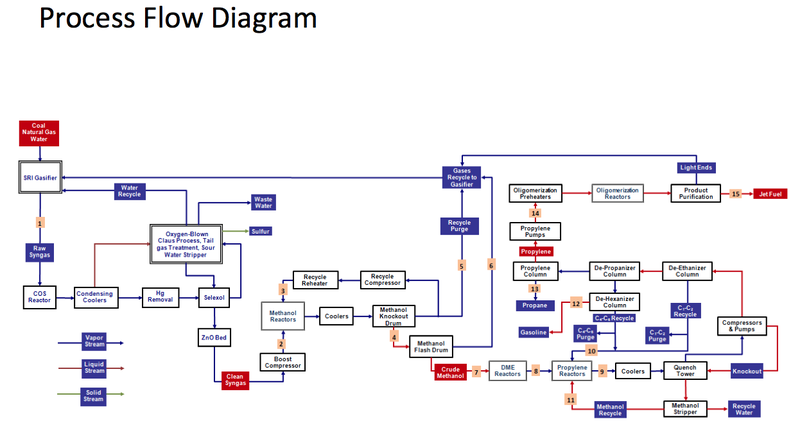
Although the process is simple, it incurs high capital and operation cost and only becomes competitive when crude. Converting gas to liquids (GTL) through the Fischer-Tropsch (FT) route to monetize stranded gas has received increasing attention over the past few years.
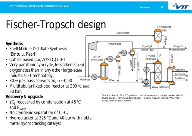
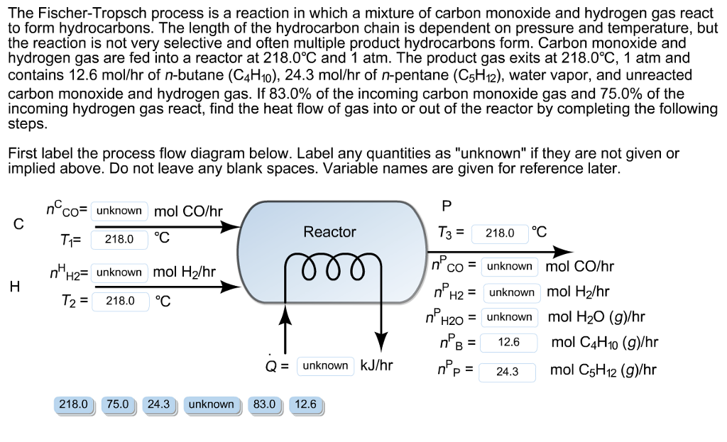
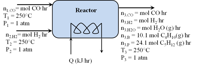
FT technology is a process that rearranges carbon and hydrogen molecules in a manner that produces a liquid, heavier hydrocarbon molecule. The Fischer-Tropsch process In the F-T reaction, synthesis gas (CO and H 2) reacts over a catalyst to produce a mixture of straight- chain hydrocarbons that can be treated to produce transport fuels.Fischer–Tropsch process – WikipediaBiofuels Academy | Dedicated to Biofuels Education in Chemical Engineering
