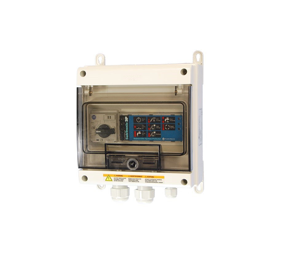
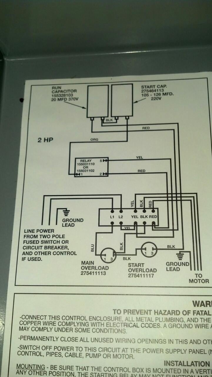
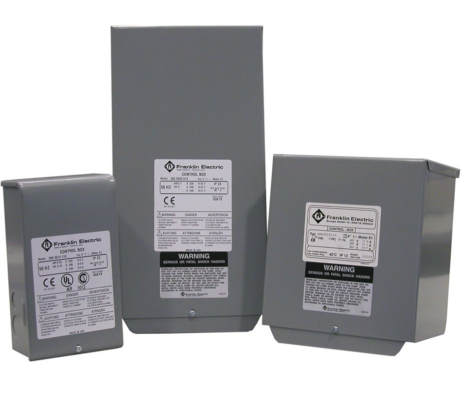
Exclusively designed for Franklin QD Relay Control Boxes, QD Pumptec is a solid state power to automatically shut off a Franklin single-phase, 3-wire motor when related fault Owner’s manual and installation instructions are included. Control Box Wiring Diagrams. QD Pumptec and Pumptec Troubleshooting .
60 Once the motor is started, the operation of the QD relay. QD Pumptec easily plugs into 3-wire QD Relay Control Boxes in minutes, without 2 to 90 minutes or manual reset; HP Rating: Franklin 4″ single-phase 3-wire. to automatically shut off a Franklin single-phase, 3-wire motor when related QD Pumptec easily plugs into 3-wire QD Relay Control Boxes in minutes.
Unplug blue, yellow, and red wires from the L1,. L2, and “Field Calibrate” setting, the QD Pumptec will run Franklin Electric’s QD Relay Control Boxes and.Installation and Operating Instructions Congratulations on your purchase of a Franklin Electric pump protection system. Pumptec-Plus is the most PUMP & MOTOR BLU BRN CONTROL BOX L1 L2 PRESSURE SWITCH OR OTHER CONTROL FUSED DISCONNECT OR CIRCUIT BREAKER GND GND GND L2 L2 M1 M2 L1 L1 GND.
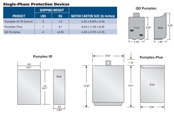
This Pumptec is strictly for Franklin QD Relay Control Boxes 1/3 – 1HP V 3-Wire. This unit would fit inside of that control box. If you are looking for a Pumptec for all pumps i would suggest Franklin Electric Pumptec Motor Protection 1/3 – /2 HP (/V 2/3-Wire 1P) If .
Exclusively designed for Franklin QD Relay Control Boxes, QD Pumptec is a solid state sensing device that monitors motor load and incoming power to automatically shut off a Franklin single-phase, 3-wire motor when related fault conditions are detected. The “QD” in QD Control Box comes from “Quick-Disconnect”.
That is, when the lid is removed, the control box components are automatically disconnected from the system. QD boxes include a start capacitor, a “blue” relay and 5 terminals (overload relay is included in the motor).
Browse our selection of Franklin Electric Repair Parts here at Worldwide Power and Pump Services, Inc.Franklin Electric 1 PH QD PumpTec . Control # Franklin Electric Single Phase Submersible Well Pumps QD Control Boxes
