DEFROST. TIMER.
Features and Benefits. Designed for commercial freezers and .
Freezer Defrost Wiring Diagrams Hvac
Applications and Wiring Diagrams. MECHANICAL.
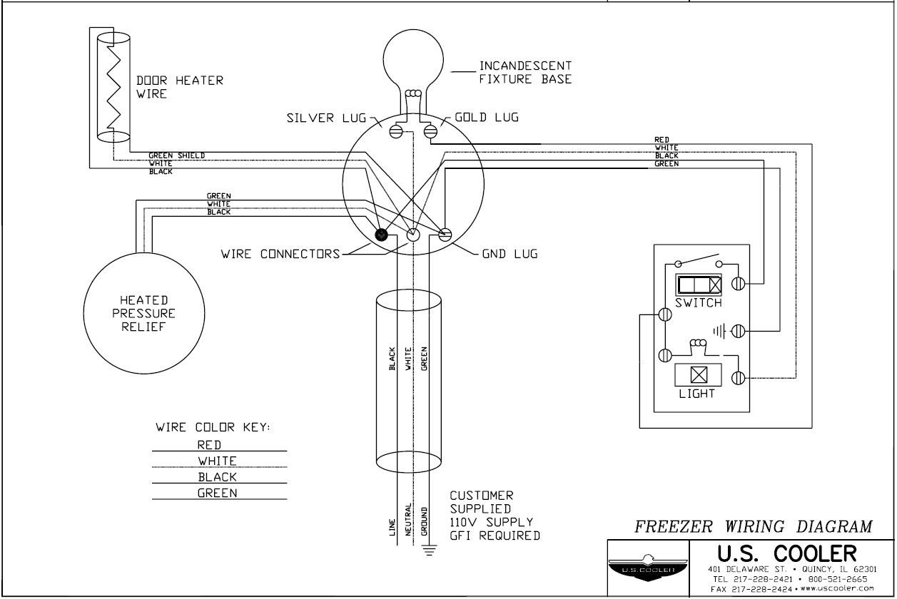
DEFROST. TIMER. Step 3: Test the defrost timer with a VOM set to the RX1 scale.
Clip one probe of the VOM to each defrost timer — not motor — wire, and turn the timer control. Defrost Timer Controls.
– Series Defrost Timers Retail store display freezers and reach-in coolers Typical line voltage wiring diagram. 3.
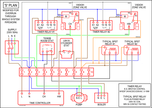
Determine . I have a generic wiring diagram that I use on all my installs that works very well.
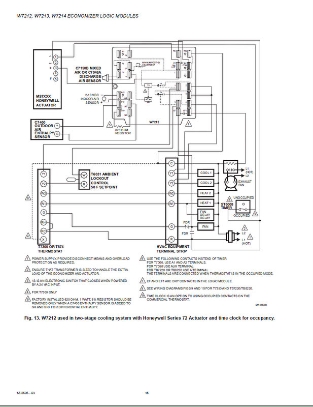
It is basically the same for most all commercial walk in freezers. We would like to bypass the timer so the machine is always set to “on”.
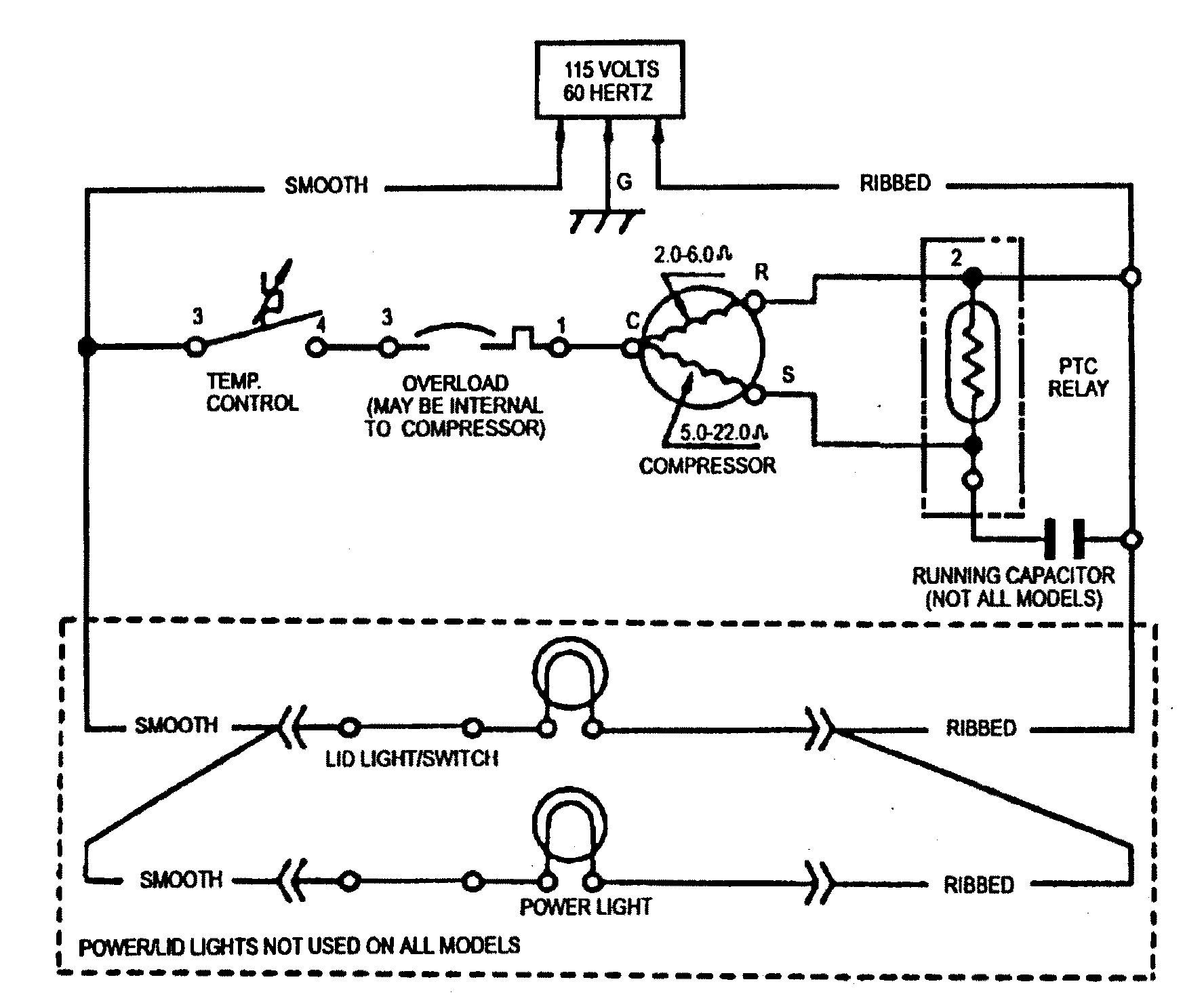
This would be a whole lot easier if you have a wiring diagram and can.Commercial Refrigeration Temperature and Defrost Controls UNI-LINE® PRODUCT KNOWLEDGE. Typical line voltage wiring diagram 3.
Determine location of sensor; Universal Defrost Timer – Wiring. Convert to Convert to Convert to N 1 4 32 X.
Mar 17, · Walk In Freezer Defrost Timer Wiring Diagram webtor from supco 3 in 1 wiring diagram, source:schematron.org How about graphic preceding? can be that amazing???.
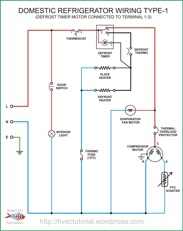
if you feel thus, I’l m show you a number of image once more down below. Jun 01, · Discuss Defrost Timer Wiring in Refrigerator & Freezer Repair.
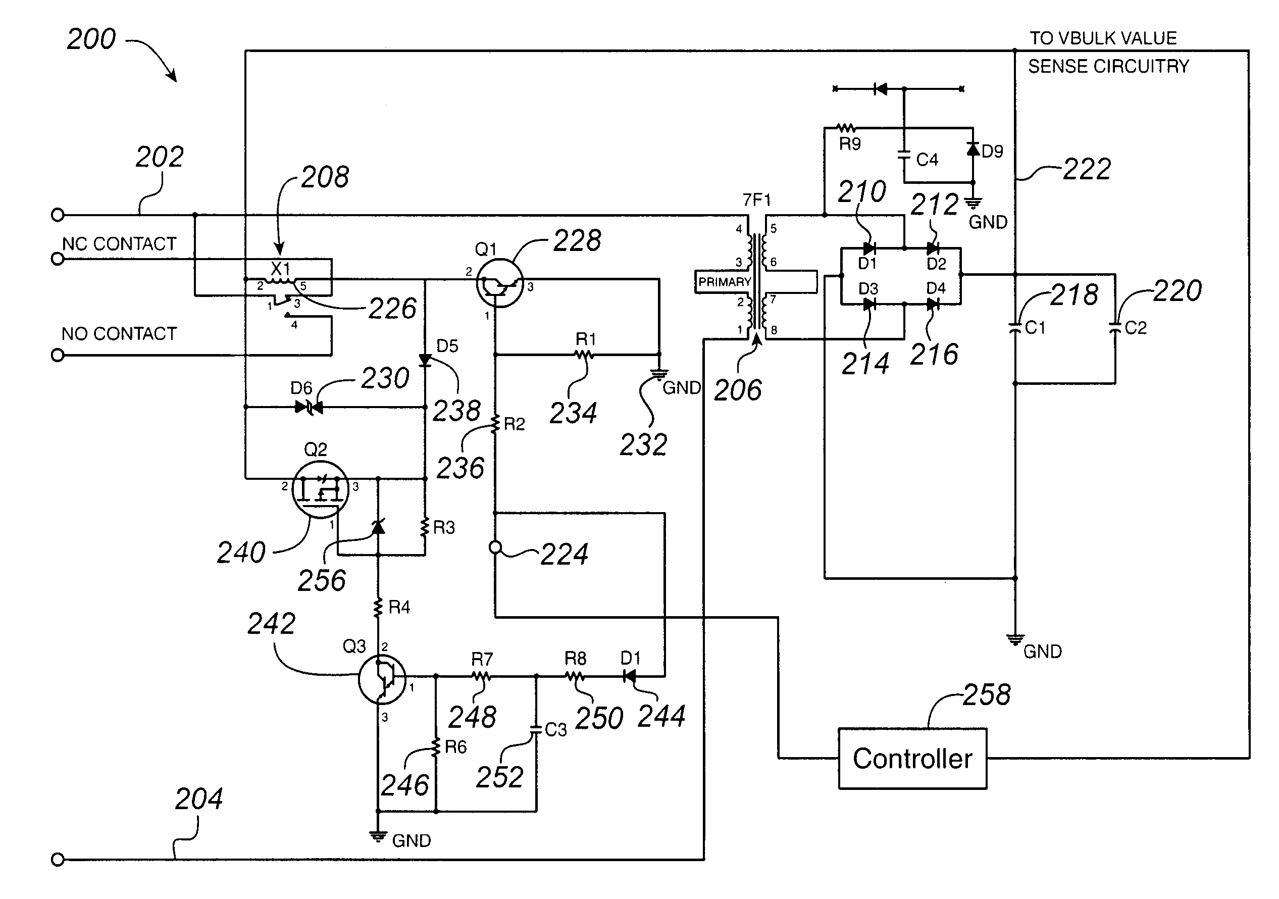
“I’m uncertain about wire connections for a replacement defrost timer for Magic Chef MCBRW. Answer Barry, make sure your defrost timer plug has the following colored wires going into the timer, black, pink, red, orange.

If you don’t have these colors, the black wire 5/5(77). This refrigerator defrost timer kit is designed to fix issues with your refrigerator temperature as well as symptoms such as the defrost cycle not working, build up of ice in the freezer, and unfamiliar noises from the timer/5(15).I need to no how to rewire an defrost timer to an – FixyaCommercial Defrost Timer Wiring | Wiring Library
