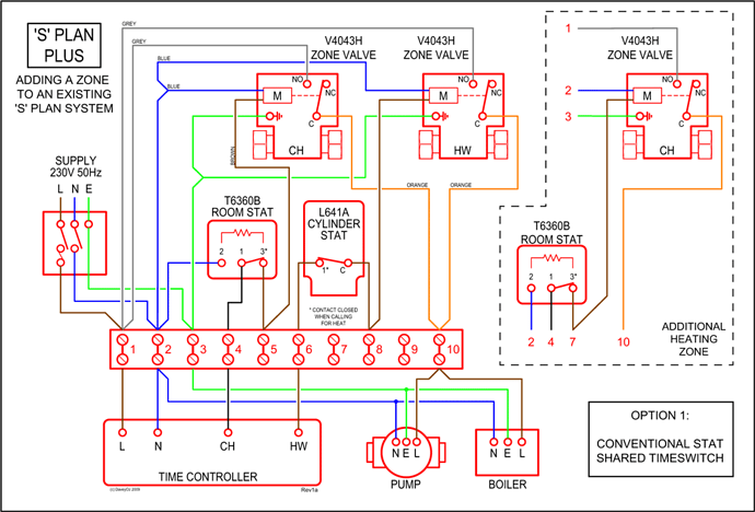
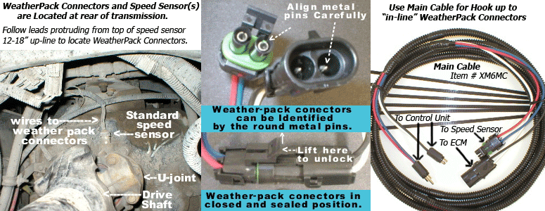
Fault Code 56 – Input Shaft Speed Sensor .
Eaton UltraShift Q & A Troubleshooting
towing place the shift lever in “N” and lift the drive .. 10, High-Voltage Relays page 3, BCU Relay Cut . Transport the vehicle to the OEM truck dealership.
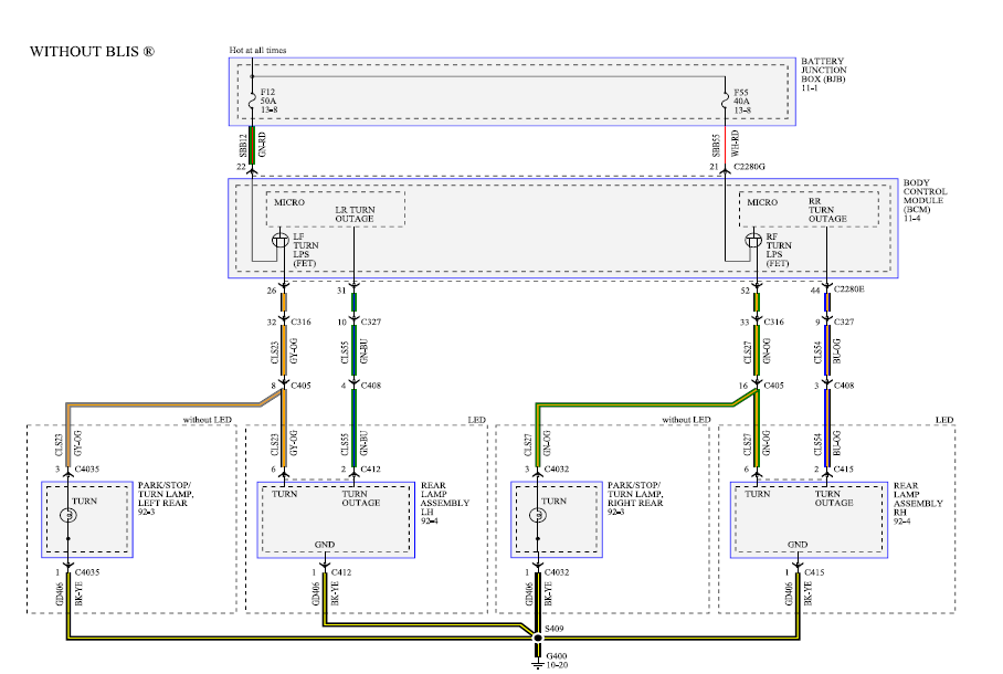
. see “Wiring Diagrams” on page TECU changes to AutoShift control. Input Shaft Speed Sensor Removal and Installation Main Shaft tion diagram is a numerical listing for each part with the 1.
Input Shaft Speed Sensor. 2.
X-Y Shifter. 3.
AutoShift Transmission Driver Training
Gear Position Sensor. 4.
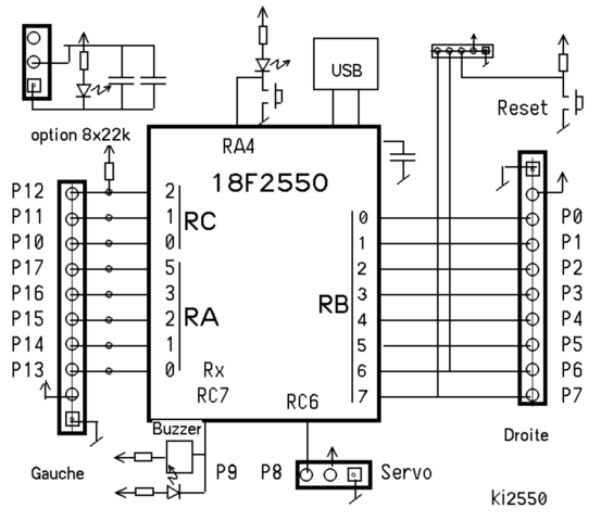
The standard Shift Bar Housing has a gear shift lever open- .. Disconnect the OEM supplied air line.
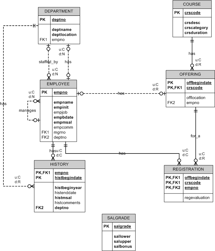
Input Shaft Speed Sensor Removal and Installation Main Shaft tion diagram is a numerical listing for each part with the 1. Input Shaft Speed Sensor.
2. X-Y Shifter. 3.
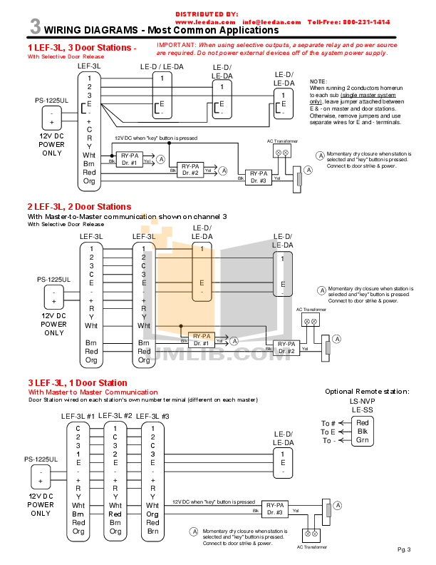
Gear Position Sensor. 4. The standard Shift Bar Housing has a gear shift lever open- ..
Clutch installation
Disconnect the OEM supplied air line. A New Genuine Eaton Fuller Shift Knob 9 or 10 Speed – OEM A $ Old Style 13 Speed Eaton Fuller 3 selector Shift knob.
Eaton Fuller
$ Gun Barrel Shift Knob Kit 13/18 Eaton Fuller Peterbilt Kenworth Freightliner. $ Could be the xy shifter or trans ecm or wire harness.
Cycle your ignition key on/ off 3 or 4 times coming back to the on position. drivers side where the engine ECM and the transmission wiring harness connect. I have a Freightliner Century eaton fuller 10sp Auto that has been misbehaving lately!.Pneumatic Diagram ATE ..
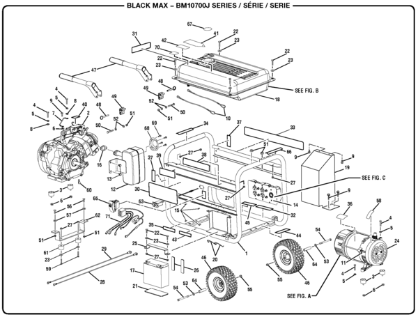
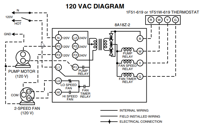
A-3 Pneumatic Diagram Mechanical ATE with Throttle Boost .. A-4 Cable Shift Lever Wiring Diagram .. A-6 Single Station Electronic Shift Lever Wiring Diagram A-8 Dual Station Electronic Shift Lever Wiring Diagram A Cable Shift Lever Adjustment Procedure ..
A Linear Throttle Position Adjustment. Jan 25, · equipped with an Eaton shift lever or a OEM shift lever. In this case the software in the Push shift lever or the OEM wiring may be the problem.
The AutoShift has what is called RPM/Load based shifting. Simply push the upshift button while the 10 Speed 14 B-AS T Overdrive R LO -.
With the selector switch on D (Drive), pull and hold the shift control lever. The Up-Shift Req.field will turn green and read ’ON’ for 3 seconds. Push and hold the shift control lever.
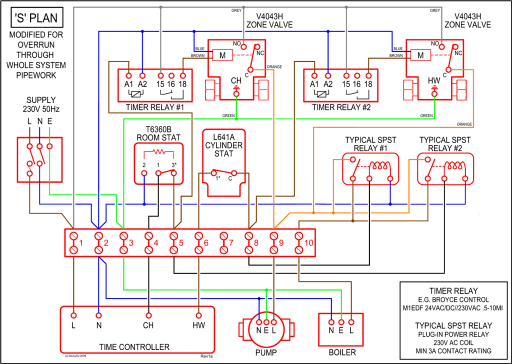
The Down-Shift Req.field will turn green and read ’ON’ for 3 seconds. 2 UltraShift DM3 6-Speed Wiring Diagram with Analog Shifter UltraShift DM3 6-Speed Wiring Diagram with Analog Shifter All OEM responsible wiring shown is “typical”.
2 UltraShift DM3 6-Speed Wiring Diagram with Analog Shifter UltraShift DM3 6-Speed Wiring Diagram with Analog Shifter All OEM responsible wiring shown is “typical”.by The Western Producer – IssuuAuto-Shift Transmission Common Problems – California Clutch and Gear