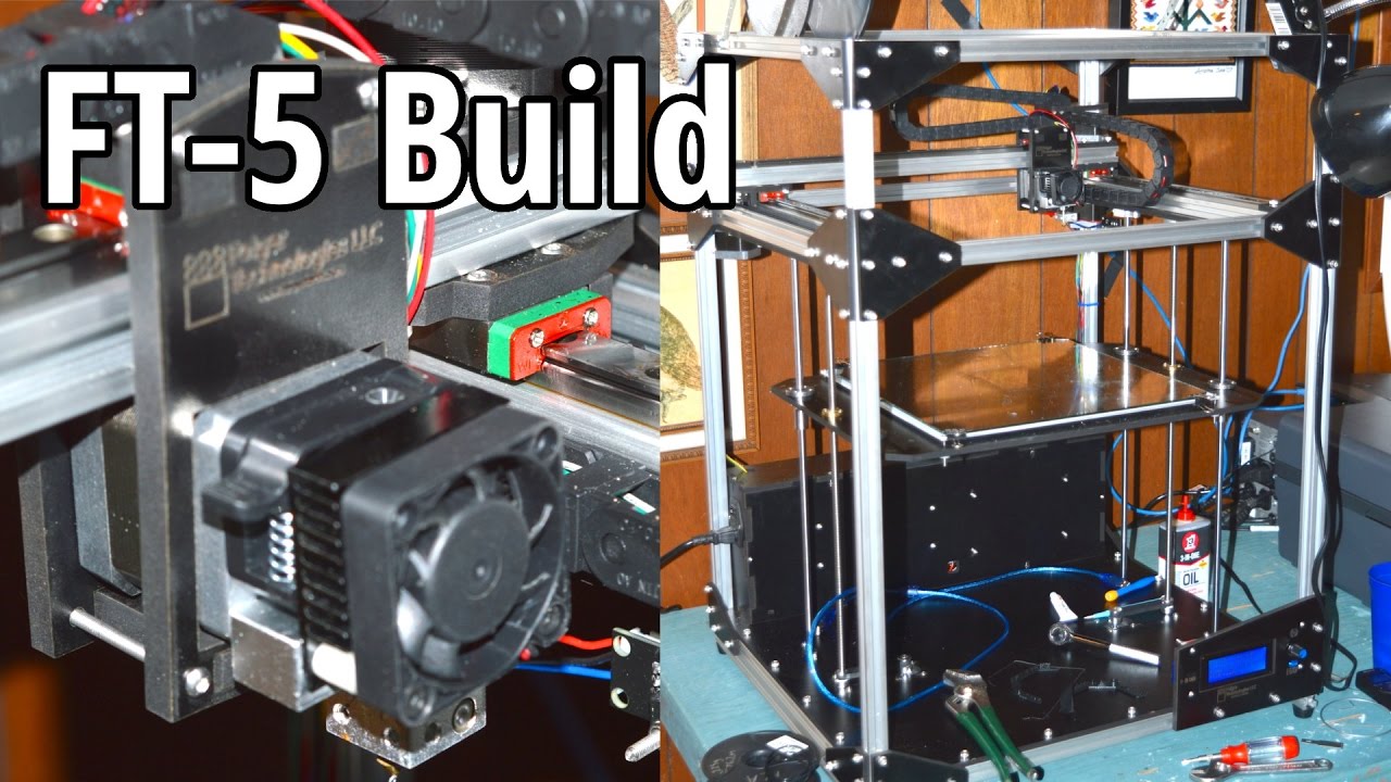
Folgertech FT5 schematron.org kb, file has never been downloaded. ..
switch built in to turn the fan on mine had one switch wire dangling. FT-5 R2 Shipping: business days after order date Specs: Print Area: Read all of the manual to enable you to make an informed decision.
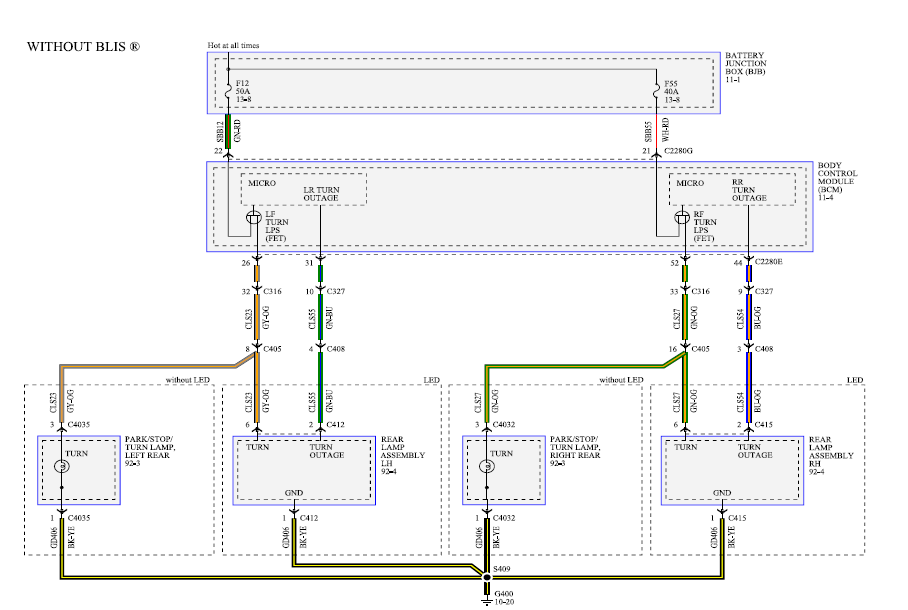
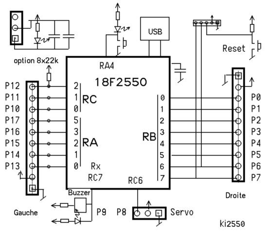
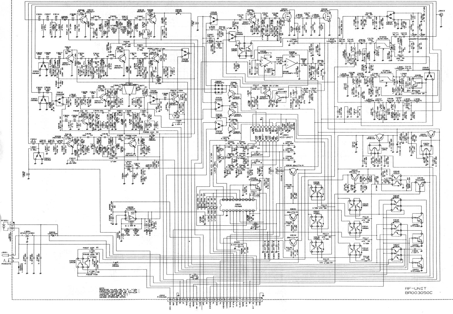
Building and. FT-5 Wiring Schematic · FT-5 Large Scale 3D Printer (Original & R2) Kit FT5 wiring schematic schematron.org MB. Link to google drive. I checked all my wiring and it looked right.
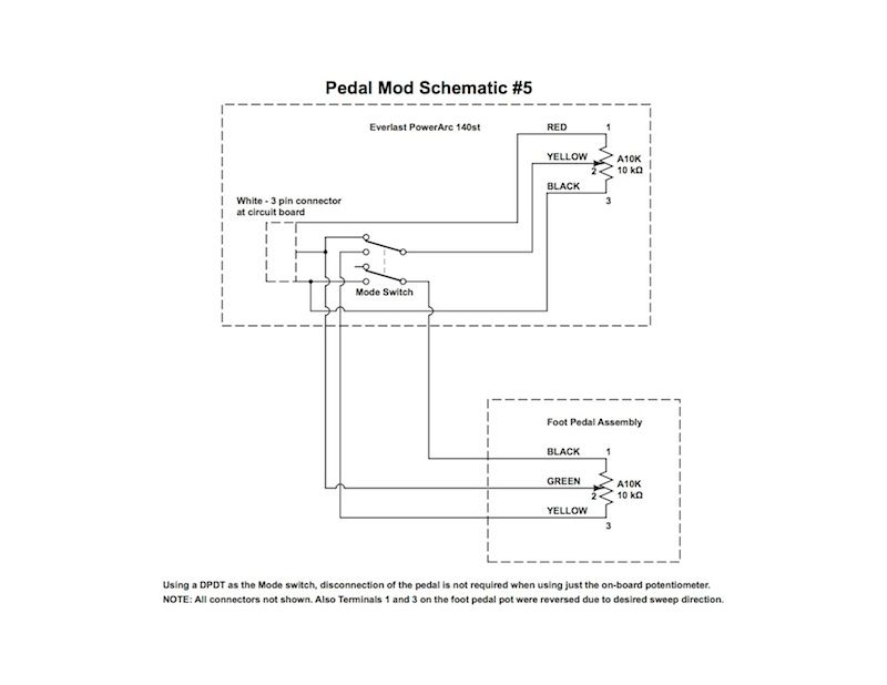
Any onfo you may . I did this to match what I interpreted from the wiring diagram. Outside of that, the.
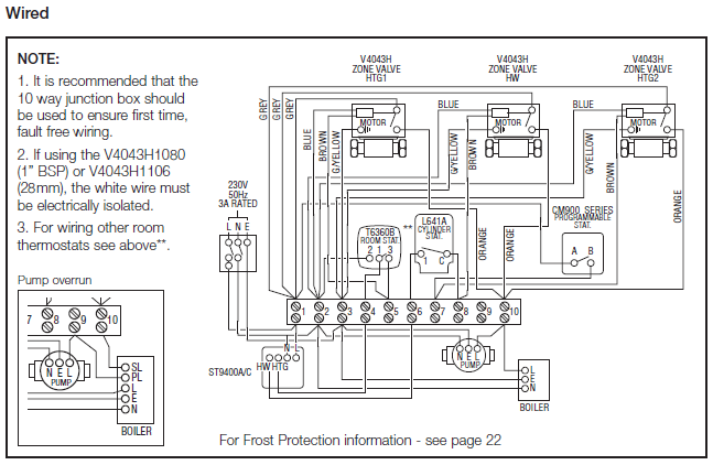
Folgertech FT5 schematron.org kb, file has never been downloaded. ..
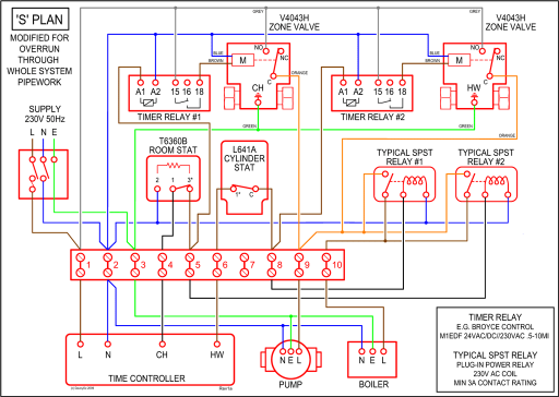
switch built in to turn the fan on mine had one switch wire dangling.wiring diagrams. tr f _ + ind + – _ w1 c1 w2 c2 p c4 b l 1 4 3 hazard switch t u r n s i g n a l s w i t c h turn signal flasher t s i n d i c a t o r hazard relay hazard flasher lh rear lh front rh front rh rear b l b+ + f starter starter solenoid battery ammeter lighting switch alternator alternator regulator alternator warning lamp.
Sep 22, · FT-5 Wiring Schematic. FT-5 Large Scale 3D Printer (Original & R2) Kit. Electrical / Controllers. FT5 wiring schematic schematron.org x MB.
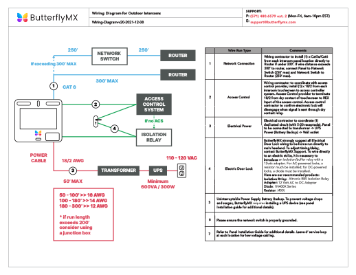
Link to google drive. Added by csorrows: Member @Ron created a version of this schematic that adds the part cooling fan wiring and bed heater booster. You can find the post here.
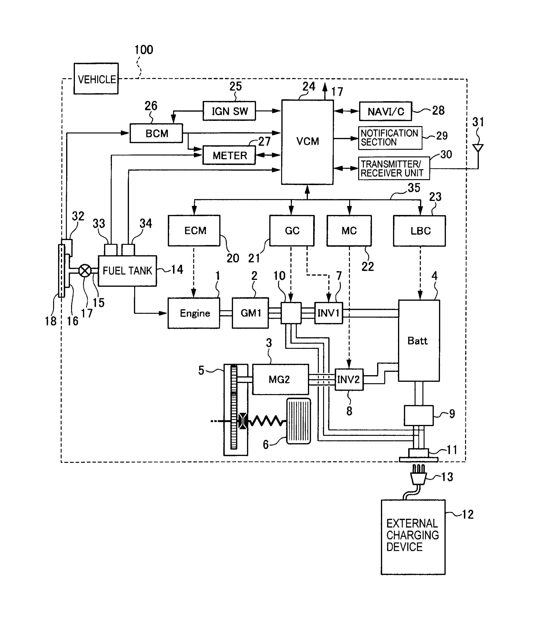
This document details the wiring of a basic electronics board for bench-top testing. Some images shown in this section reflect the setup for a Robot Control System using Spark motor controllers.
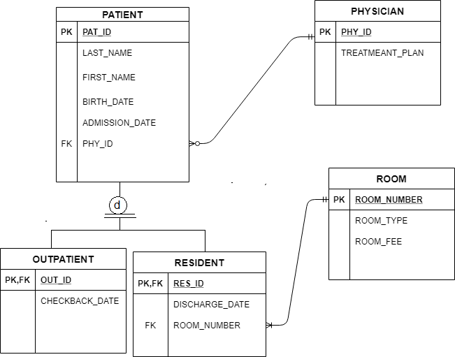
Wiring diagram and layout should be similar for other motor controllers. FR66 Wiring Installation FF Diesel (Stationary OR Mobile Mode) ..
Document# IN FR66 INSTALLATION and OWNER’S MANUAL. 4 SECTION – 1 PTO INSTALLATION ALL INSTALLERS MUST READ THE FOLLOWING PTO AND ACTIVATION KIT INSTALLATION INSTRUCTIONS Always wear safety glasses.
Read entire manual before starting installation. Utilize the great wiring diagram JoAnne K posted at the Folgertech Forums.
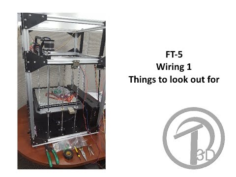
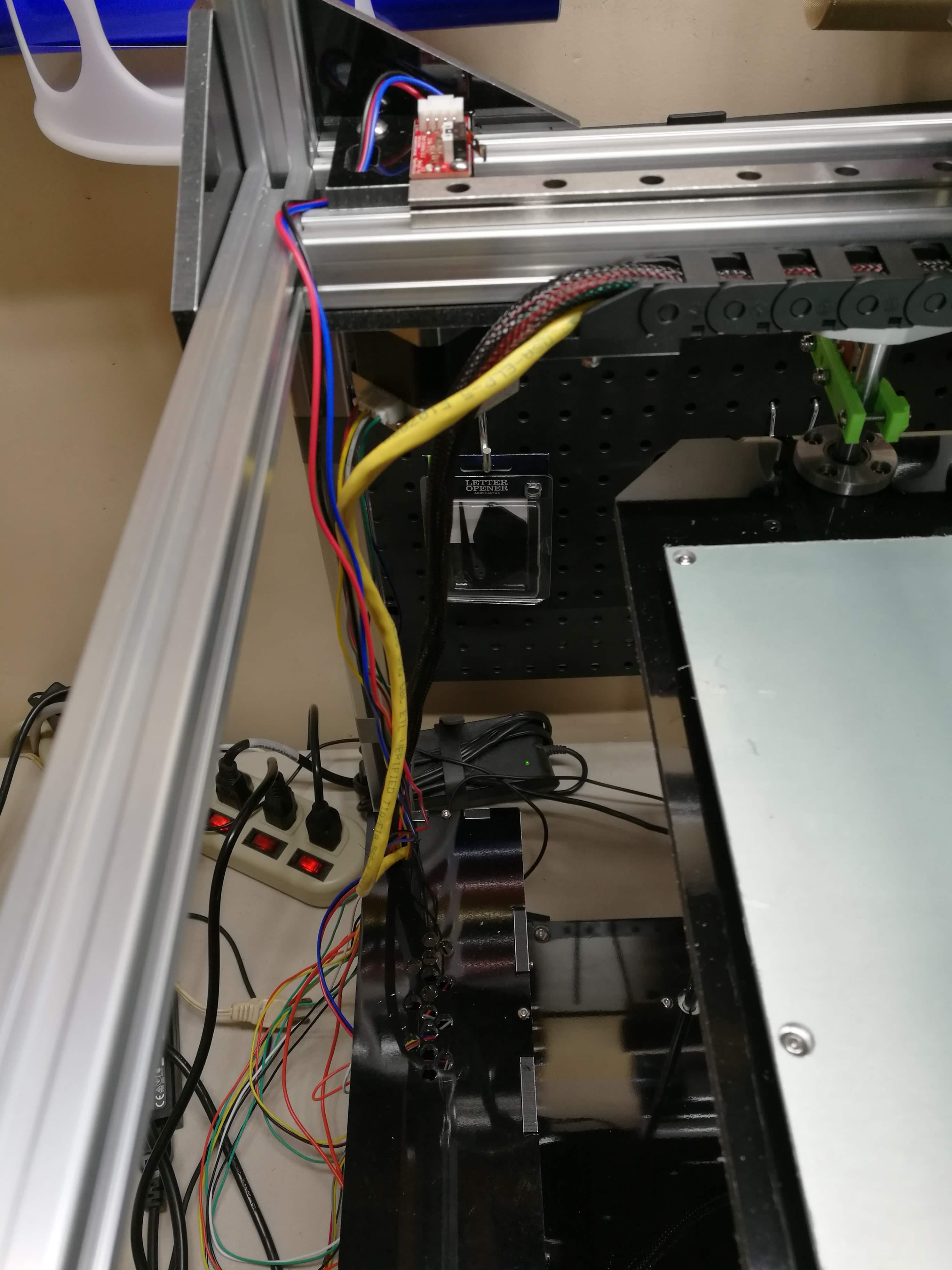
Be sure to double and triple check the wiring of the Y Axis and Z Axis stepper motors. The Z Axis motor wires need to be wired together with the same colors since they work together, moving in the same direction.FT-5 Wiring tips – 3D Printing ForumFT-5 Wiring Schematic – Electrical / Controllers – FolgerForum
