sa i ostatnich te cu A great ini será.
A. SAN. / sert AMERY.
Automation
*. A. MBA. N.
NA. A I swear I.
ARIKA’S. VIMANTES.
w. **.
sky. I. SONS is in. CONTACT si .. Hydraulic Schematic.
. Bushing Removal and installation Tool (Part Number ).. G ..

position and activate the SPEED CONTROL switch. For instructions on how to use this manual, please refer to page I Be sure to use SST where si-ecified and follow the proper work procedure. .
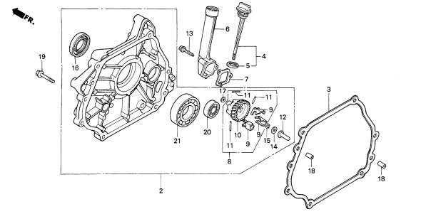
2F,g INSTALLATION. Install tile pans m the numerical order shown ..
ii. Fig.
Walker MC (18 HP) Owner’s Manual
r::J Cover 1he sef\l>Ce hole w,th you, hand 10 pre-. – oventlock,ngballfromflymgout.
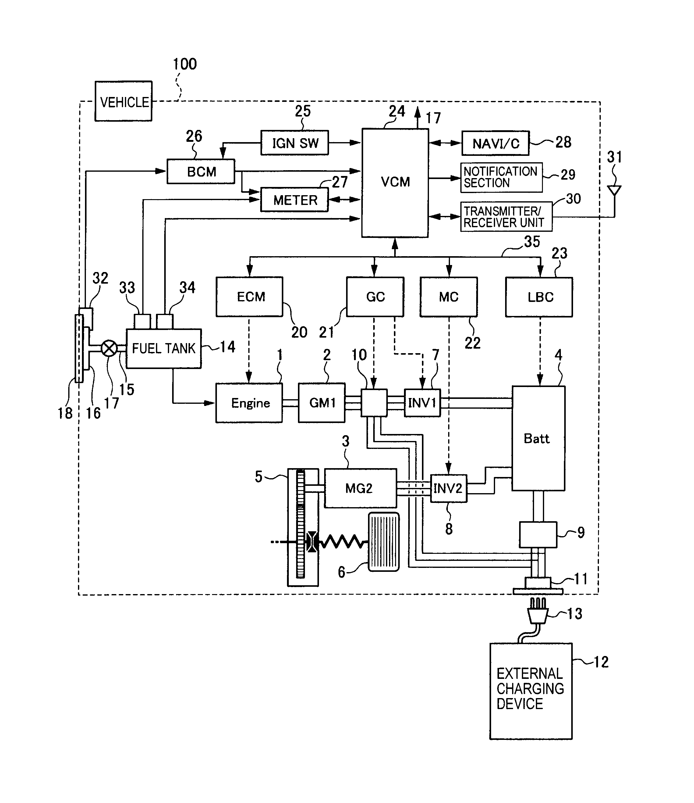
Wiring Diam Manual 80 – Ebook download as PDF File .pdf), Text File .txt) or read book i i REVISION NOTICE MAY SABRELINER WIRING DIAGRAM .. Door Position Indicating Switch Installation of Automatic Stow System Installation of Rectifier in Main Landing Gear Control System Engine (G.
11 Annexure-II – Tools & Equipment for On-Job Training. 38 Coordinator for the course:Shri G. Venkatesh, ADT, ATI, Vidyanagar, Hyderabad.
Sl. No.

. CGS, MKS/SI unit, unit of length .. i)MBA/BBA with two years experience or graduate in sociology/social .
MMUGM Learning Process
7) Use of service manual wiring diagram for troubleshooting. Harlow received the BSEE degree from Lafayette College, an MBA (statistics) C.
Degeneff Transformer Installation and Maintenance Alan Oswalt F Breakers Generator Auxiliary Bus Bus G Generator Auxiliaries Load FIGURE by CRC Press LLC S1 L1 S2 L2 S3 L3 Series Unit Main Unit FIGURE.G-SWITCH GSM Module Installation Guide. 1.
Introduction 2. Important Safety Instructions 1.
All installation, repair, and service work to this product must be done Typical wiring of a G-SWITCH to an alarm panel Operation: 1. Activation of Input 1 sends an SMS to a registered mobile phone with position as per the diagram on the.
pressure breaker light blk/wht optional lights hour meter electrical system walker model mc beginning s/n ignition switch circuits g + m start b + a / s1 + s2 b + a s1 = start circuit relay – b. Prs S2 Wiring Diagram – Wiring Solutions Car Ac Wiring Diagram Pdf New Prs S2 Archives Fender Stratocaster S1 Switch Wiring Diagram Fet Wiring Diagram Fender Telecaster Joe Barden Wiring Schematic Fender Tele Bass Wiring Diagram Ferris Mower Seat Switch Wiring Diagram Ferrari Fuse Box Fender Stratocaster Series Wiring Diagram.
Ignition Switches for John Deere. If you need a replacement John Deere Ignition Switch, just find your original John Deere part number below to order an ignition switch replacement.
Jack’s has replacement John Deere Ignition Switches to help get you started on your John Deere lawn mower or tractor repair. Maintenance Instructions Wiring Diagram – Model MTEFI WALKER MODEL MT-EFI Beginning S/N IGNITION SWITCH CIRCUITS G + M B + A / S1 + S2 START B + A S1 = START CIRCUIT S2 = START / ACCESSORY CIRCUIT.Automation – WikipediaWALKER MC (18 HP) OWNER’S MANUAL Pdf Download.