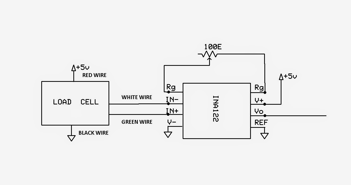
Load Cell Wire Colors. Click Help!
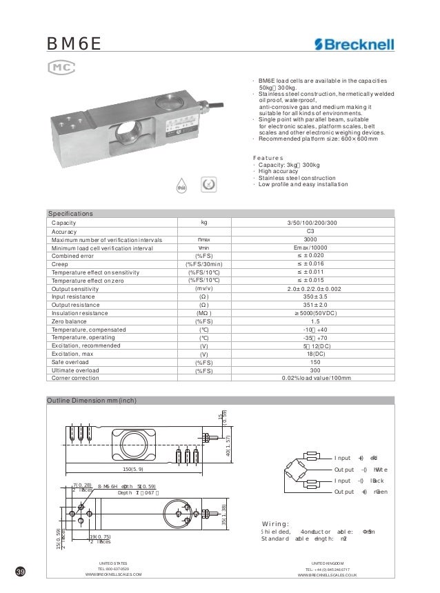
For Color Code Choices By Model Number. Manufacturer, Models, + Excitation, – Excitation, + Signal, – Signal, Shield.
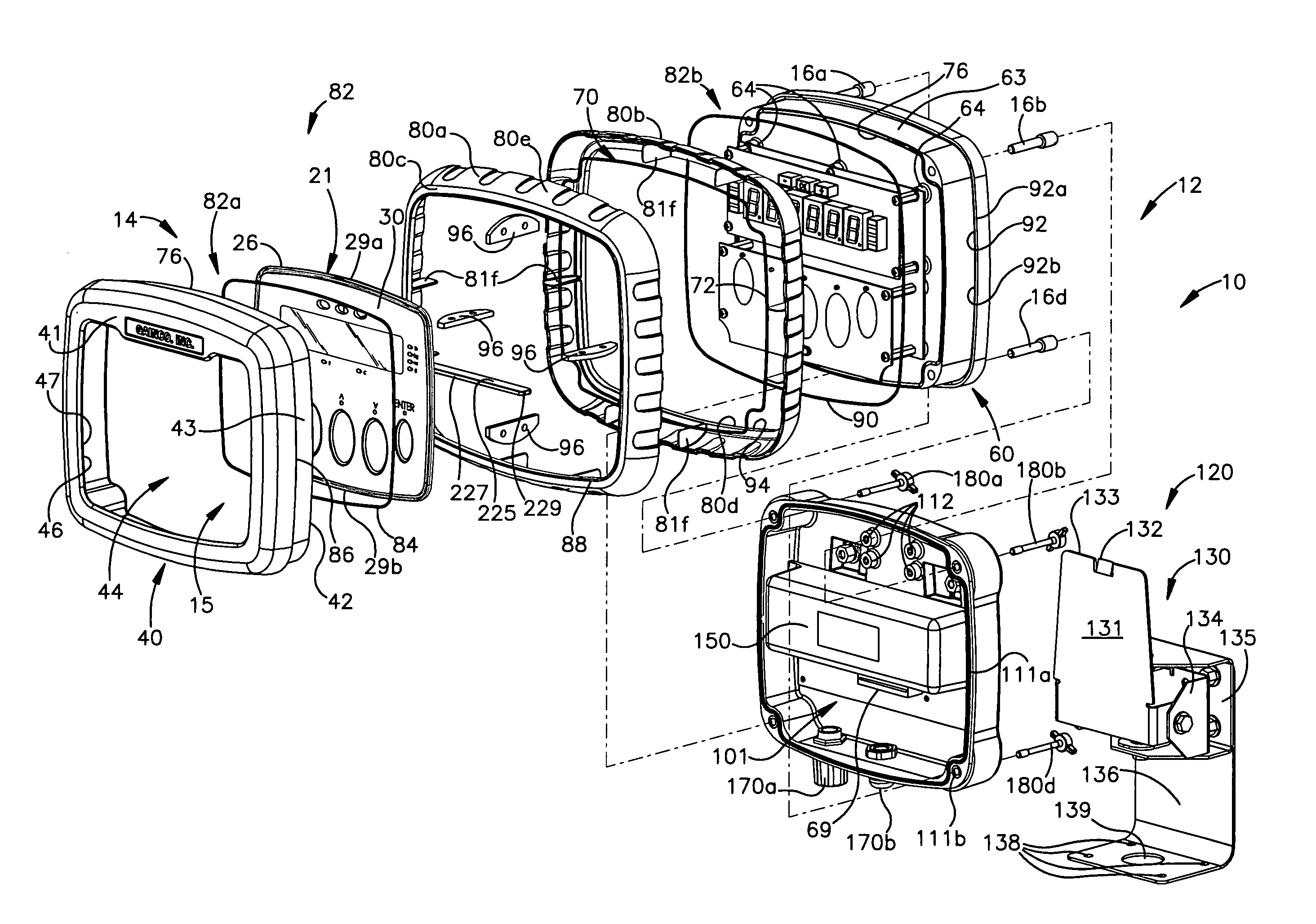
schematron.org . Series Load Cells II Gainco Launches Portion Sizing Application Digital for Years through (includes corresponding Graph/Chart) II Attached you will find a color code chart covering the standard load cells and load sensors offered by Hardy Instruments, and another chart that.
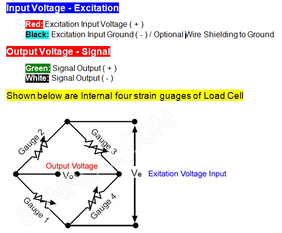
With 4-wire extension cables the load cell output should be connected to pairs of diagram of three signal trimmed load cells. To avoid an interaction problem. Attached you will find a color code chart covering the standard load cells and load sensors offered by Hardy Instruments, and another chart that.Manufacturer: Models + Excitation – Excitation + Signal – Signal: Shield + Sense – Sense: A&D Engineering: RED: WHITE: GREEN: BLUE: YELLOW: Allegany: GREEN: BLACK.
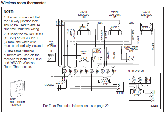
“Flatshift” Quick Setup guide (Load cell) These instructions must be followed exactly! 1.

Connect the red wire from the shift ECU harness to an ignition 12v supply. 2. Connect the Black wire from the shift ECU harness to the power ground.
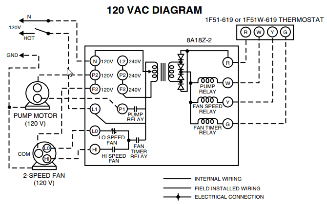
3. Connect the 3-pin female . Scales react strongly toward magnetic fields.
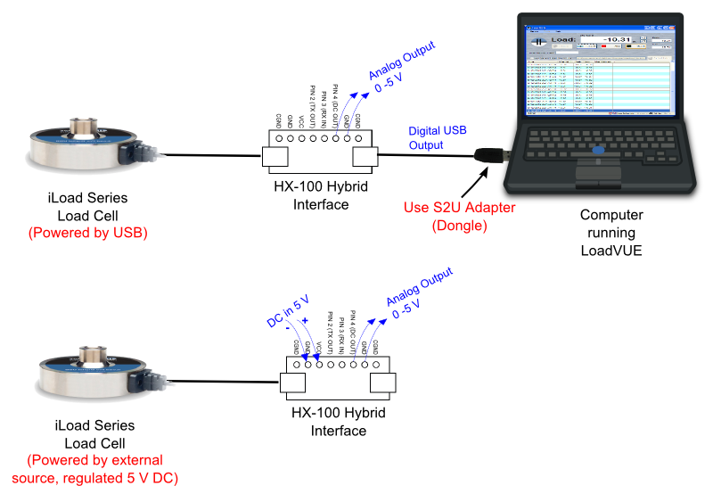
We recommend you do not use your scale near a computer, monitor, radio, cell phone, or television. If you place a cell phone near your scale you will visually see the scale reacting to its field. Load Cell Torque Sensor.
Online Support | Smart Tools | Extraneous Load Factor. Extraneous Load Factor; A How To Calculate Extraneous Loads (55 KB) FSH (18 KB) FSH (18 KB) FSH (18 KB) FSH (18 KB) FSH (18 KB) FSH (18 .

Load Cell Wiring Guide. Quickly reference which wires represent signal, excitation and sense lines for almost any given load cell brand and model.
To download from available app stores, go the the Scale Tools home page.What is the wiring color code on my load cells? How can I verify it is correct?Load Cell Wiring Guide