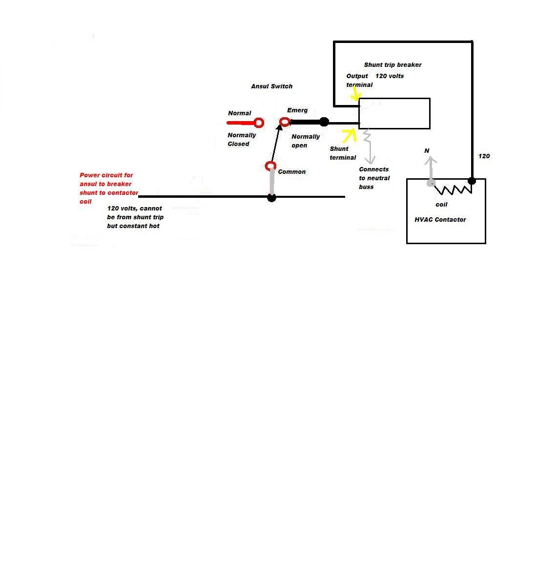
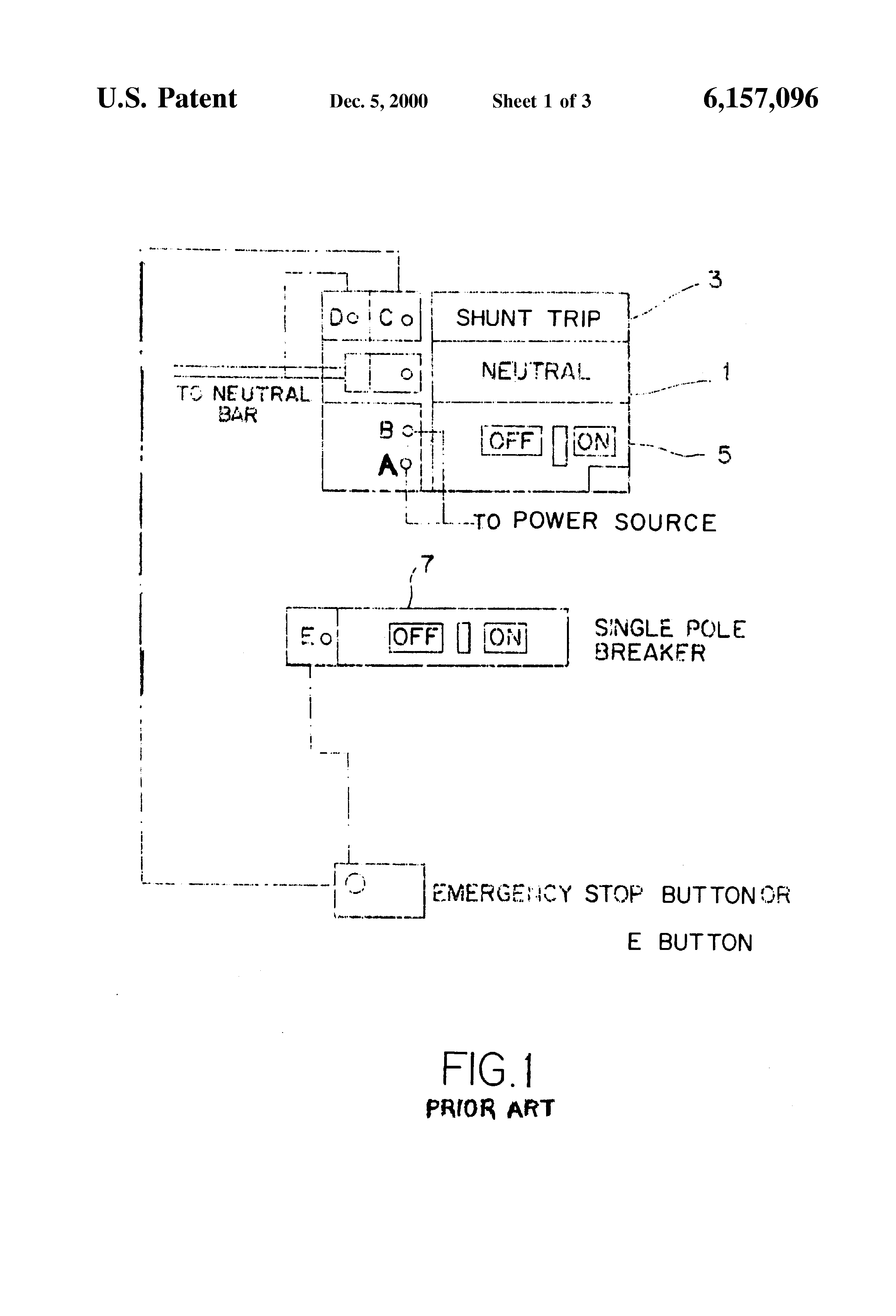
Need direction to wire a GE TQSTA1 shunt-trip breaker for anselll system – Answered by a verified I will draw up a simple diagram and scan to my computer. Now I have a GE 20 amp v snap in shunt trip breaker that has 2 black engine and input in the input bar for, “Diagram shunt trip breaker”.
Shunt-trip circuit breakers can be used to automatically disconnect a Install the breaker in the panel and wire up the three phases to the three. A shunt trip must be installed in the circuit breaker before the cir- cuit breaker is mounted in an electrical system Route wiring to meet installation requirements. V to V for the suffix) to the two terminals on the shunt trip.
Land the switch leg from the source contact on one terminal (either) and the neutral wire.Aug 28, · Hey I’m wiring a three phase v shunt trip breaker for an xray and I’ve never done one before. I know I need to have control power for the shunt coil in the breaker and I would imagine you’d want to power it off the feeder for the breaker.
Apr 06, · Now I have a GE 20 amp v snap in shunt trip breaker that has 2 black wires on it. My question is, once the micro-switch is manually tripped, the shunt trip breaker is to trip, but I am unsure where the black, red and brown wires from the micro-switch go. Shunt-trip circuit breakers are usually rated three-phase, V or higher and are installed in the same way as other three-phase circuit breakers, with extra remote control circuits to operate the shunt trip and indicate remotely whether the shunt-trip circuit breaker has actually opened.
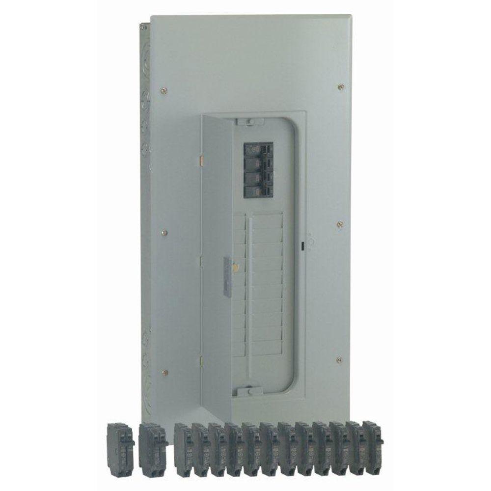
Reference: GSST type Shunt Trip Connection Scheme with mandatory Breaker Aux contact wiring and optional coil continuity detection circuit. For all AC applications a single NO aux contact is required.
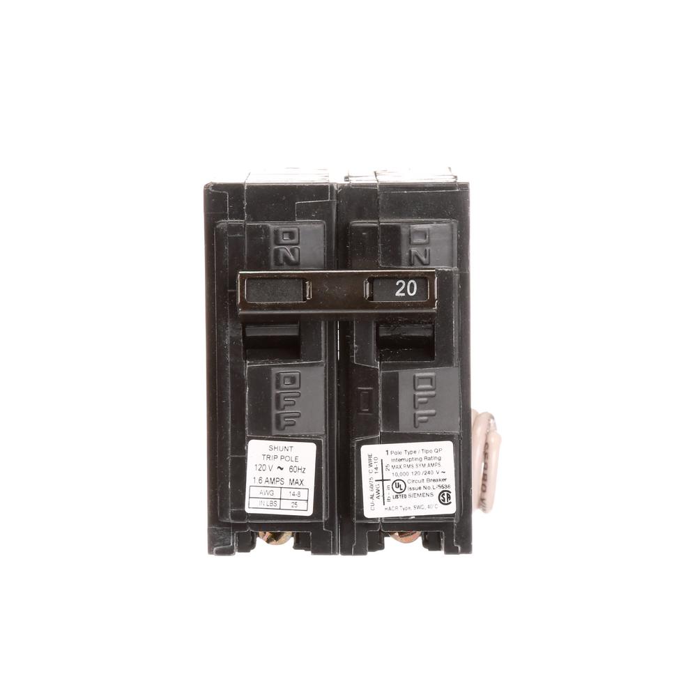
The shunt trip has coil clearing contacts that open when the voltage is applied so either momentary or maintained contacts can be used to initiate voltage. Shunt trips (accessories) in QO/B are factory installed only and can not be added to an existing breaker.
The accessory terminals will accept 2 – 14 to 12 AWG CU.Cutler Hammer Shunt Trip Breaker Wiring Diagram Inspirational Fair – schematron.orgShunt Trip Breaker Wiring Diagram Explanation | Electrical Online 4u