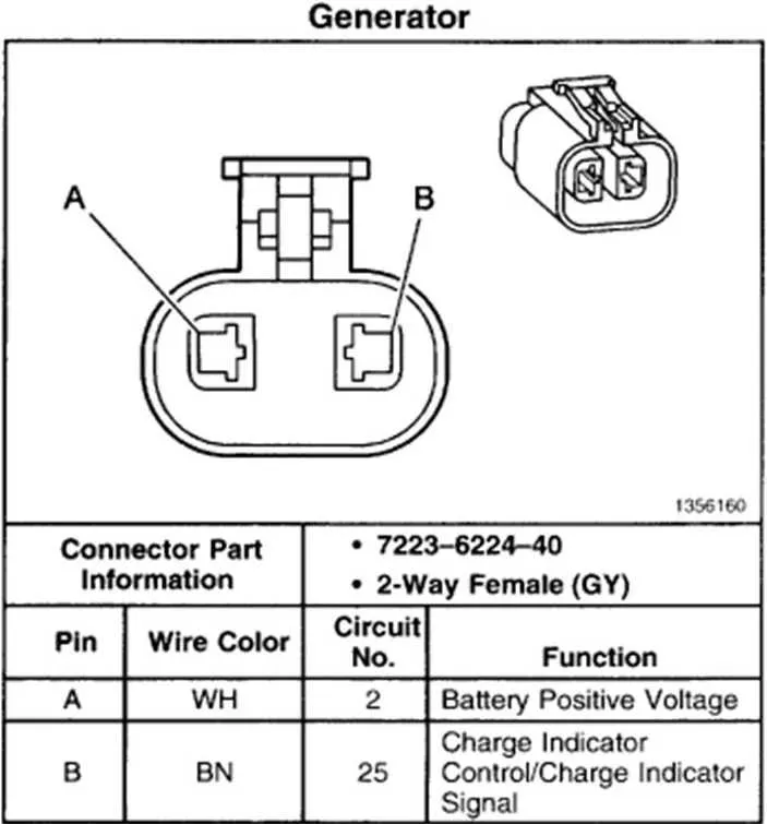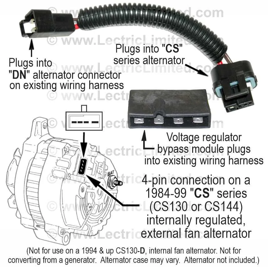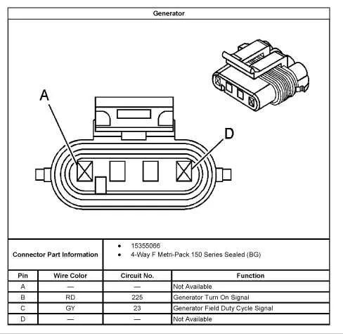
To successfully connect a GM 2-wire charging unit, begin by identifying the main connections: the primary output and the excitation terminal. The larger terminal typically connects to the battery, providing the necessary charge, while the smaller terminal is responsible for initiating the system once the engine starts running.
Primary Output Terminal: This should be securely linked to the positive terminal of the battery or the power distribution block. Ensure there is no loose connection, as this will impact overall performance.
Excitation Terminal: This connection requires a regulated 12V signal, typically from the ignition switch or a voltage regulator. It activates the charging process as soon as the engine begins turning over.
Tip: A common issue is a poor connection at the excitation terminal, often leading to the system not charging. Double-check for clean, tight connections and appropriate wiring insulation to avoid grounding issues.
In case of troubleshooting, verify that the voltage is consistent at both terminals during operation. If the voltage is low at either point, inspect the wiring for damage or corrosion, and replace any affected components to restore optimal functionality.
GM 2 Wire Charging System Connection Guide

To properly set up the 2-wire charging system for GM vehicles, follow these steps for correct installation and functionality.
- Terminal 1: Connect this terminal to the vehicle’s battery positive terminal. This ensures the charging system gets power and provides the necessary output to the battery when needed.
- Terminal 2: This terminal links to the field control circuit. It acts as the regulator input for voltage management. Ensure the connection is secured and clean to avoid erratic performance.
For the most efficient operation:
- Make sure both connections are free from corrosion or wear.
- Ensure the connections are tight to prevent voltage drop and power loss.
- If using a newer system, verify the proper sensor connection to ensure stable voltage readings.
After making the connections, check the system’s voltage output with a multimeter. It should read between 13.5V and 14.5V when the engine is running, indicating correct function.
Understanding the Two-Wire Setup

When dealing with a two-wire system, the first connection to focus on is the “B+” terminal. This terminal should be connected directly to the battery or another power source, providing the necessary voltage to keep the system operational. A good connection here is crucial for the proper functioning of the entire electrical system. Ensure the contact is clean and secure to prevent voltage drops.
The second connection is typically tied to the field control mechanism. This terminal regulates the voltage output based on demand. It’s vital to connect this terminal to the appropriate control circuit, usually through a voltage regulator, to maintain consistent output under varying loads. This part of the system often includes an additional ground connection to stabilize the operation and prevent spikes in voltage that could damage sensitive components.
Both connections must be free of corrosion and damage. Inspect the terminals regularly, as poor connections can lead to unstable performance or even complete system failure. It’s advisable to use high-quality connectors that fit snugly and securely to prevent accidental disconnections.
How to Properly Connect the Wires on a GM 2 Wire Alternator
Ensure the main terminal is securely attached to the positive battery terminal. This is essential for proper voltage regulation. The second terminal should be connected to the vehicle’s charging system to trigger the charging process when the engine starts. Make sure this connection is tight to avoid power loss or malfunction.
Use high-quality connectors to guarantee a solid and corrosion-resistant connection. A ring terminal crimped onto the end of the lead is recommended for the main connection. Tighten it using a torque wrench to the manufacturer’s specified settings to avoid over-tightening, which could damage the components.
For the secondary terminal, ensure the connection is routed through the ignition switch and connected to the “sense” line. This line detects the voltage in the electrical system and helps maintain proper voltage regulation.
Before finalizing, verify that the connections are clean and free from any dirt or corrosion that could impede the flow of electricity. If necessary, apply dielectric grease to the connectors to protect against corrosion over time.
Troubleshooting Common Issues with 2 Wire GM Alternators
Check for loose connections at both the positive and ground terminals. Tighten any loose connections to ensure proper conductivity and avoid inconsistent charging. Pay special attention to the ground, as poor grounding often leads to voltage irregularities.
Inspect the excitation signal from the regulator. If the voltage is inconsistent or absent, the charging system won’t function. Use a multimeter to check the voltage at the field terminal. It should be around 12 volts when the engine is running. If not, there could be a problem with the regulator or the signal source.
Verify the diode trio is functioning correctly. A malfunctioning diode trio will lead to improper power generation. To test, check the output voltage across the system at idle and higher RPMs. Any dips or fluctuations could point to a faulty diode trio, requiring replacement.
Ensure the belt is correctly tensioned. A loose belt can cause insufficient rotation, leading to inconsistent performance. Check for wear or slippage and replace the belt if necessary. Proper tension is critical for maintaining consistent voltage production.
If voltage readings are consistently too high or too low, check the voltage regulator settings. An incorrect regulator can cause overcharging or undercharging, damaging the battery and other components. Adjust the regulator or replace it if it’s not maintaining the correct voltage.