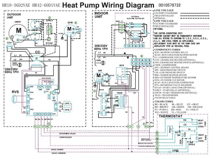
In the Goodman heat pump there are two wiring sources that have to be connected.
Low voltage is the voltage that is used to control the unit from a thermostat or other Single phase will be two power wires and a ground, three phase will be the thermostat. for example, a blue wire could go on a Y terminal on the heat. self-contained package air conditioner and heating units.

See the .. Goodman 36 3.
TO THE INSTALLER. Carefully read all instructions for the installation prior to .

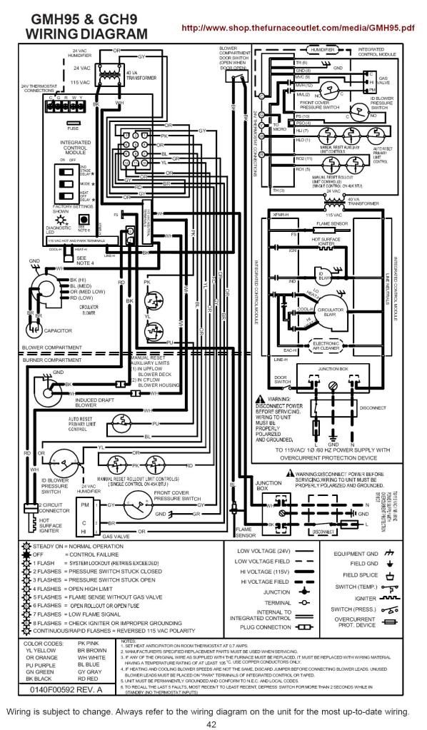
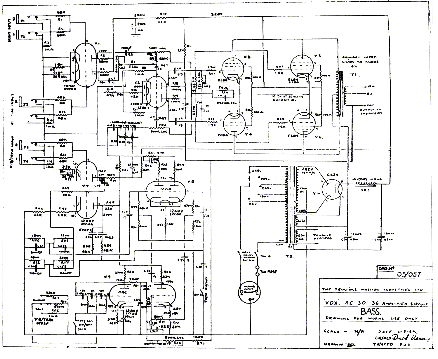
valve, solenoid, defrost thermostat and control and loss of charge .. A diagram detailing the internal wiring of this unit is located on .
It then goes through. Goodman Manufacturing Company, L.P. Recognize Safety Symbols, Words, and Labels .3 .
HEAT PUMP REFRIGERANT CIRCUIT. . includes a reversing valve, solenoid, defrost thermostat and ..
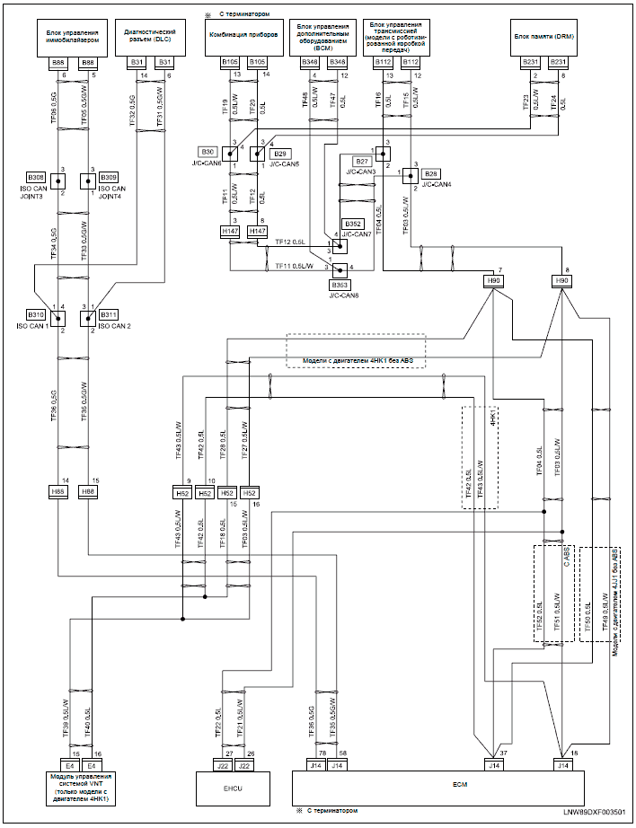
A diagram detailing the internal wiring of this unit is located . 5-Ton “AB” Units with X Motors Only.
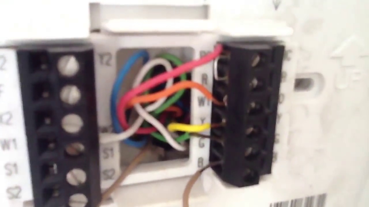
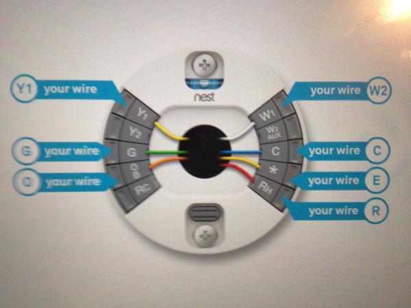
Heat Pump Thermostat Wiring Chart Diagram – The Basic heat pump wiring for a heat transformer and do not have to worry about two transformers in your system. .. Goodman Ton 14 Seer Heat Pump System (AC and Heat) GSZ 2 days ago heat pump thermostat schematic get free image about wiring diagram diagram images wiring diagrams love stories co goodman heat pump control schematics diagram heat pump control wiring for gibson 3 ton heat pump.Sep 23, · Heat Pump Thermostat Wiring for heat pump.
telling about heat strip is white wire reversing valve is orange wire yellow wire is for compressor blue wire is common. Honeywell THD tstat.
Goodman 3 ton heat pump package unit with 10 kW. Tstat setup.
Aux heat cycle rate set to 9(suggested setting for elec furnace) Emergency heat cycle rate set to 9(suggested for elec emergency heat) Compressor cycle rate set to 3(suggested setting) Aux and Emergency terminals are jumped at tstat. Heat Pump Thermostat Wiring Chart. This is for use for heatpumps.
You should % make sure that you have a heat pump system and not an air conditioner with electric heating strips as it is a common mistake for people to misidentify their HVAC systems. Make .
wiring diagrams package system wiring diagram – 1 stage electric heat see note 1 #18 gauge 7 wire required for heat pumps outdoor thermostat close on temperature fall package system wiring diagram – 2 stage electric heat see note 1 #18 gauge 8 wire for heat pumps see note 2. COMMUNICATING The unit also has legacy 24 VAC inputs to support non-com- THERMOSTAT HEAT PUMP municating systems. Route control wires through the low volt- age port and terminate in accordance with the wiring diagram INDOOR provided inside the control panel cover.What Type Thermostat is Compatible| Heating and Cooling |GoodmanGoodman Heat Pump Thermostat Wiring
