2 high-precision inputs for strain gauge. Measuring ranges adjusted with nominal characteristic values upon delivery. Manual entry of.
In this manual “inverter” or “inverters” refers to the inverter models: SGI , SGI , SGI , minimum wire gauge and temperature rating of the wires. This unit can recalibrate an ignition system tachometer signal.
Wiring: PWR – Set DIP switches #3 and #4 for the cylinder count the gauge is designed for. Maximum cable lengths are based on the wire gauge of the standard power cables.

Consult . Chassis Branch Circuit Diagram for VAC, 15 amp, 3- wire Wiring SGI Series Deskside and Onyx2 Deskside Chassis Branch Circuits. These gauges can be mounted in-dash or in Auto Meter mounting solutions ( panels, proper functioning of this instrument, please read instructions thoroughly.(See diagram on the next page for connections) Standard Case 3.
Connect a wire to the gauge stud marked “S” (signal) and secure with nut and lock washer. Connect opposite end to the fuel level sender’s signal wire or terminal.
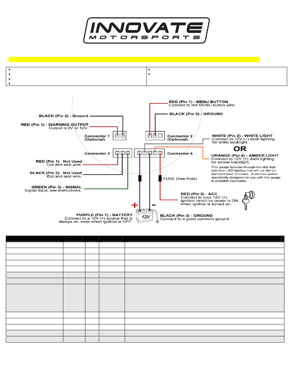
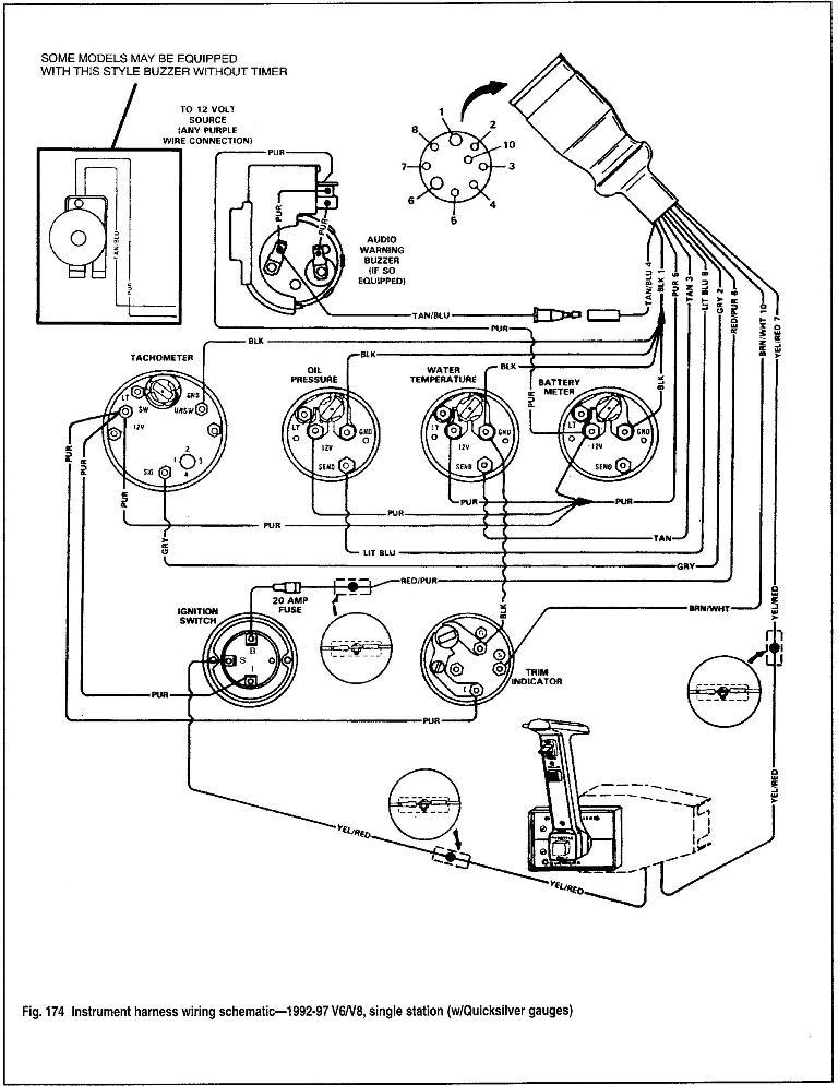
It is recommended that insulated wire . Large Scale Model Railway Basics By the mid ’s, G scale was firmly established, and several manufacturers were offering a broad range of rolling stock and locomotive products for sale (though scale ratios vary between to , depending upon manufacturer). Wiring Diagram Wiring the gauges: Run the power wiring from the gauges to an appropriate positive (+) on the fuse block after the battery.
This applies to the switched 12V+ and gauge lighting Connect the ground to a good dedicated ground on the chassis Run each wire to the appropriate sender and use the proper connector for each item. Electrical Wiring: Refer to the wiring diagram, Diagram G. Wire gauges in series from a positive (+) accessory to a source which is not already overloaded with fans, air conditioning, and such.
The ground (Œ) wire is also run in series, including the light socket ground. The final ground run, using gauge wire, should be connected to a good.
Wire a fuel gauge by first disconnecting the old dysfunctional unit to replace it with a new one. Obtain volt power from the fuse box using a standard wire, and connect it to the positive terminal of the fuel gauge.Appendix B.
Site Power and Power Cables12 Volt Wiring: Wire Gauge to Amps | schematron.org