
A hand off auto ladder diagram is a type of electrical control circuit diagram that is commonly used in industrial settings. This diagram is used to control various motor-driven devices, such as pumps, fans, and conveyors. It allows for automatic and manual control of these devices, giving operators flexibility and ease of use.
The hand off auto ladder diagram consists of multiple rungs, each representing a different component or action in the control circuit. It typically includes three main elements: the hand control, the auto control, and the off control. These elements allow operators to choose between manual operation (hand control), automatic operation (auto control), or shutting down the device (off control).
In the hand control mode, the operator has direct control over the device. They can start and stop the device using a push button or other similar control device. This mode is useful for troubleshooting or when the operator needs precise control over the device.
In the auto control mode, the device operates automatically based on preset conditions or inputs. This mode is commonly used when the device needs to run continuously or when specific conditions need to be met for the device to operate.
The off control mode allows the operator to shut down the device completely. This mode is used when the device needs to be stopped for maintenance or other reasons. The off control is typically activated by a switch or button that overrides the hand or auto control modes.
What is a hand off auto ladder diagram?
A hand off auto ladder diagram is a type of electrical diagram commonly used in industrial settings to control machinery or equipment. It is a graphical representation of the electrical circuit using ladder logic symbols to show the interconnections between different components.
The hand off auto (HOA) function is typically used in situations where an operator needs to control the operation of a machine or equipment manually, automatically, or by using a combination of both. The ladder diagram for HOA control consists of three sections: the hand (manual) section, the auto (automatic) section, and the off section.
In the hand section, the operator can manually control the operation of the machine by activating or deactivating specific components. This can be done by pressing physical buttons or switches. The hand section is often represented by a rectangular shape in the ladder diagram, with inputs and outputs connected to the buttons or switches.
The auto section is responsible for the automatic operation of the machine or equipment. It includes sensors, relays, timers, and other components that are used to control the sequence of operations. The auto section is usually represented by a series of horizontal ladder rungs connected to each other, showing the logical flow of electricity.
The off section is used to stop the operation of the machine or equipment completely. It is typically represented by a normally closed (NC) contact connected to a stop button or switch. When the stop button or switch is pressed, the normally closed contact opens, breaking the circuit and stopping the flow of electricity.
In essence, a hand off auto ladder diagram allows for the flexibility to manually control the machine, automatically control it, or shut it off completely, depending on the needs of the operator or the specific situation. It provides a clear visual representation of the electrical circuit and allows for easy troubleshooting and maintenance.
Understanding the Basics of Ladder Diagrams
A ladder diagram is a graphical programming language used in industrial automation systems. It is primarily used to program the logic of relay logic control circuits and programmable logic controllers (PLCs). Understanding the basics of ladder diagrams is essential for anyone working in the field of industrial automation.
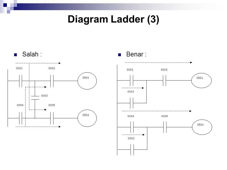
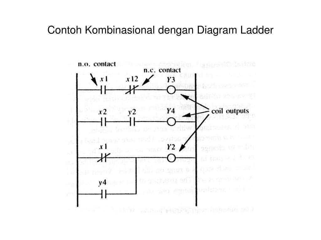
In a ladder diagram, the logic of a control circuit is represented by a series of “rungs” that run horizontally across the page. Each rung consists of inputs (represented by contacts) and outputs (represented by coils or relays). The ladder diagram is read from left to right and from top to bottom, just like reading a book.
The basic elements in a ladder diagram include normally open (NO) and normally closed (NC) contacts, coils, and power rails. A normally open contact represents a condition that must be met for the circuit to be activated, while a normally closed contact represents a condition that must not be present for the circuit to be activated. Coils are used to control outputs, such as turning on a motor or activating a solenoid valve.
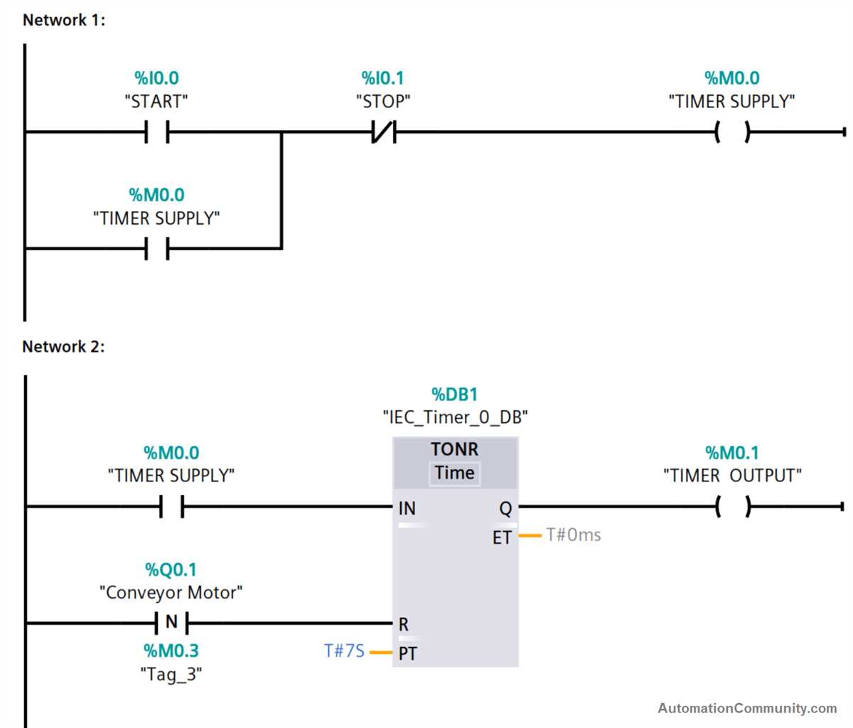
Within a ladder diagram, there are also various programming tools and instructions that can be used to control the logic of the circuit. These include timers, counters, and comparison instructions. Timers can be used to introduce delays into a circuit, while counters can be used to keep track of the number of times a certain condition has occurred.
Overall, ladder diagrams provide a visual representation of the logic of a control circuit, making it easier for industrial automation professionals to design, program, and troubleshoot complex control systems. By understanding the basics of ladder diagrams and how to read and interpret them, professionals in the field can effectively design and program control systems for a wide range of industrial applications.
Key components of a hand off auto ladder diagram
Hand off auto (HOA) ladder diagrams play a crucial role in controlling industrial machinery, especially in scenarios where operators need to manually control the equipment or let it function automatically. These diagrams are commonly used in electrical control systems and consist of various key components that facilitate the control and operation of machines.
1. Motor control circuit
The motor control circuit is one of the main components of a hand off auto ladder diagram. It includes all the necessary devices, such as contactors, overload relays, and start/stop buttons, for starting, stopping, and controlling the motor. These devices are interconnected through a series of contacts and coils in the ladder diagram to ensure the proper functioning of the motor.
2. Hand-OFF-Auto switch
The hand-off-auto switch, also known as the HOA switch, is a key component that allows the operator to manually control the equipment or switch it to automatic mode. It typically consists of a three-position switch with hand, off, and auto positions. The switch is connected to the ladder diagram, enabling the operator to select the desired mode of operation.
3. Control relays
Control relays are used in hand-off-auto ladder diagrams to switch circuits on and off based on certain conditions or signals. They can be activated by the motor control circuit or other control devices, such as limit switches or sensors. Control relays allow for the control of multiple components and ensure the smooth operation of the machinery.
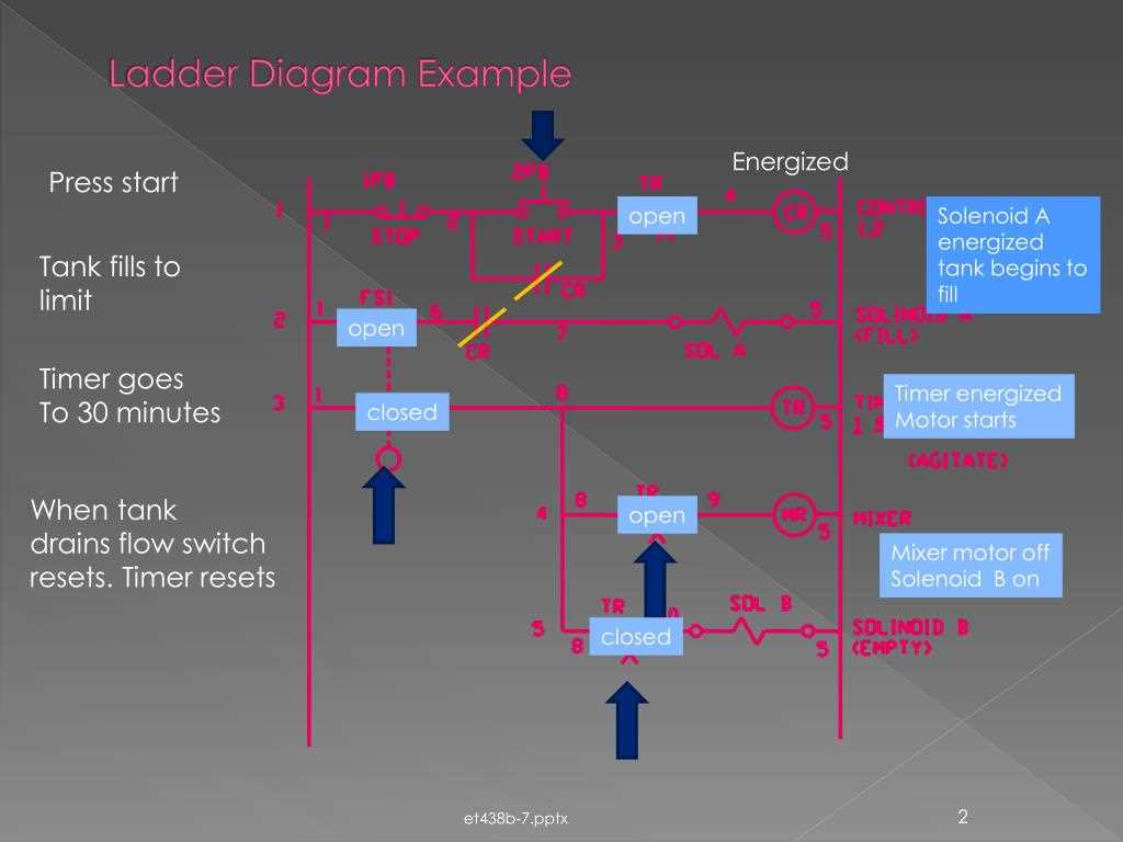
4. Timers and timers contacts
Timers are important components in hand off auto ladder diagrams as they introduce delays in the operation of the machinery. They can be used to control the duration of certain processes or to sequence different actions. Timer contacts are the logical representation of timers in the ladder diagram and are used to enable or disable specific sections of the circuit based on the timing requirements.
5. Pilot lights and indicating devices
Pilot lights and indicating devices are used to provide visual feedback to the operator regarding the status of the equipment. They can indicate whether the machine is in hand, off, or auto mode, as well as provide information about various conditions, such as motor running, fault detection, or process completion. These devices enhance the safety and efficiency of the equipment operation.
In conclusion, the key components of a hand-off-auto ladder diagram include the motor control circuit, hand-off-auto switch, control relays, timers and timer contacts, and pilot lights and indicating devices. These components work together to enable manual and automatic control of machinery, ensuring safe and efficient operation in industrial settings.
How does a hand off auto ladder diagram work?
A hand off auto ladder diagram is a commonly used electrical control circuit diagram. It is used to control the operation of motors, pumps, and other electrical devices in an automated system. The diagram consists of a series of rungs that represent different control functions, with electrical symbols and lines connecting them.
The hand off auto ladder diagram typically includes three modes of operation: hand, off, and auto. In the hand mode, the device is controlled manually using a switch or button. The off mode is used to turn off the device completely. The auto mode allows the device to operate automatically based on certain conditions or inputs.
Each rung in the hand off auto ladder diagram represents a specific control function. The rungs are connected in series, which means that the output of one rung is connected to the input of the next rung. This allows for sequential control of the device and ensures that the device operates in the desired manner.
When the hand mode is selected, the control circuit bypasses the automatic control and allows the operator to control the device manually. This can be useful for troubleshooting or maintenance purposes. In the off mode, all power to the device is disconnected, ensuring that it is completely turned off. In the auto mode, the device operates automatically based on the inputs and conditions specified in the ladder diagram.
Overall, a hand off auto ladder diagram provides a visual representation of the control sequence for a device or system. It allows for easy understanding and troubleshooting of the control circuit, and ensures that the device operates safely and efficiently.
Applications of Hand Off Auto Ladder Diagrams
Hand off auto (HOA) ladder diagrams are widely used in the field of industrial automation to control various processes and equipment. These ladder diagrams provide a visual representation of the electrical circuit and logic used to control the operation of devices and systems. They are particularly useful in applications where operators need to manually control a process or equipment, but also require an automatic mode for continuous operation.
Control of Motors
One common application of hand off auto ladder diagrams is in controlling electric motors. HOA ladder diagrams can be used to control the start, stop, and automatic operation of motors, ensuring that they function correctly and safely. The diagram may include elements such as motor starters, pushbuttons, and interlock devices to prevent unsafe conditions.
Lighting Control
HOA ladder diagrams can also be used to control lighting in industrial and commercial buildings. They can provide a simple and efficient way to switch between manual control, automatic control, and off states. For example, the diagram may include inputs from light sensors to automatically turn on lights when ambient light levels are low, while still allowing manual control when needed.
Pump Control
Pump systems are another application where HOA ladder diagrams are commonly used. These diagrams can control the start, stop, and automatic operation of pumps, ensuring that the system operates efficiently and avoids potential issues such as pump overload or dry running. The diagram may include elements such as float switches, control relays, and level sensors to monitor and control pump operation.
Conveyor Control
In manufacturing and material handling processes, conveyors are often used to transport products or materials. HOA ladder diagrams can be used to control the start, stop, and automatic operation of conveyors, ensuring smooth and efficient transportation. The diagram may include elements such as limit switches, motor starters, and interlock devices to ensure safe and reliable operation.
Overall, hand off auto ladder diagrams have a wide range of applications in industrial automation, offering a flexible and intuitive way to control various devices and systems. Whether it’s controlling motors, lighting, pumps, or conveyors, these diagrams provide a standardized and efficient method for both manual and automatic control.
Ladder diagrams are a popular way to represent electrical circuits and control systems. One type of ladder diagram that is commonly used is the hand off auto (HOA) ladder diagram. HOA ladder diagrams are often used to control motors or other equipment with multiple control modes, such as manual, automatic, and off. Here are some tips for creating and interpreting hand off auto ladder diagrams:
1. Understand the symbols
In order to create and interpret hand off auto ladder diagrams, it is important to understand the symbols used in the diagram. Some common symbols include normally open and normally closed contacts, coils, and timers. Familiarize yourself with these symbols and their meanings before attempting to create or interpret ladder diagrams.
2. Plan your ladder diagram
Before creating a ladder diagram, it is important to plan out the logic of the circuit. Determine the control modes and the conditions under which each mode should be activated. This will help you organize the ladder diagram and ensure that it accurately represents the desired logic.
3. Use clear and concise labeling

When creating a ladder diagram, it is important to use clear and concise labeling. Label each rung and each component with a descriptive name or number. This will make it easier to understand and troubleshoot the ladder diagram in the future.
4. Test the logic
After creating a ladder diagram, it is important to test the logic to ensure that it functions as intended. Use a simulation software or physically test the circuit to ensure that each control mode is activated and deactivated correctly.
5. Document the ladder diagram
Once the ladder diagram is created and tested, it is important to document it. This can be done by creating a drawing or diagram that clearly represents the ladder logic. This documentation will be useful for troubleshooting, maintenance, and future reference.
By following these tips, you can create and interpret hand off auto ladder diagrams effectively. Whether you are designing a new control system or troubleshooting an existing one, ladder diagrams can be a valuable tool for understanding and controlling electrical circuits.