To properly configure an electrical system that automatically manages power distribution, ensure you correctly wire the relay setup. Begin by focusing on the relay’s connection to the power source and the device it controls. A reliable connection ensures the device switches on and off based on the system’s demands without manual intervention.
For maximum efficiency, use a high-quality relay with clear voltage specifications, tailored to handle the device’s power requirements. Make sure the components’ ratings match to avoid overheating or malfunction. Keep the relay near the device it controls, minimizing wire length to reduce potential energy loss.
Integrate a control circuit that can detect the status of the power system and trigger the relay appropriately. It’s essential to test the setup with different load conditions to ensure the relay switches reliably without delay. Check the wiring connections for any potential issues, as poor connections can lead to system failure over time.
In case of troubleshooting, always start by inspecting the primary relay contacts and the triggering mechanism. Verify each part of the circuit for continuity and proper voltage levels to ensure everything functions as expected. For more complex setups, consider incorporating fuse protection to safeguard against short circuits and overloads.
Automatic Control Circuit for Device Switching

Ensure proper connection of the relay by following the standard layout for controlling device transitions. First, connect the control terminal of the relay to the desired signal source. The other end should be connected to the load device’s terminal, with the relay acting as a mediator between the two. Ground the negative terminals to complete the loop. For safety, include a fuse in series to prevent overcurrent situations.
Relay Activation: The control signal should trigger the coil to activate the relay, allowing current to pass through to the connected device. Depending on the relay type, ensure the polarity and voltage ratings match the required parameters to avoid malfunction.
Important: Make sure to use a relay with appropriate current handling capacity for your device to ensure long-term stability and to avoid potential damage to either the relay or the device.
For higher efficiency, place a diode across the relay’s coil to absorb voltage spikes that may occur during deactivation. This protects the rest of the circuit from potential damage caused by back EMF.
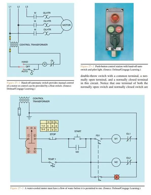
Understanding the Basic Components of a Hand-off Control Circuit
To build an effective control system for automatic switching, several core components must be understood. These parts ensure seamless operation and reliable transitions between different states in the circuit. Below are the key elements to consider:
- Relay: The relay serves as the primary mechanism for switching between circuits. It is an electromagnetic component that, when energized, alters the path of current flow, enabling or disabling devices as needed.
- Contacts: Contacts are the physical connections within a relay. They can be normally open (NO) or normally closed (NC), depending on whether they allow current flow in their default state.
- Control Inputs: These are the signals that trigger the relay’s operation. Control inputs may come from manual sensors, automated devices, or preset timers, depending on the system design.
- Power Source: A stable power supply is critical for energizing the relay and ensuring proper functioning of all connected components. The voltage and current specifications must align with the relay’s requirements.
- Load Devices: These are the elements that are being controlled, such as motors, lights, or other electrical appliances. The relay connects or disconnects these devices based on the control signals received.
- Timer (if applicable): In some configurations, a timer can be integrated into the system to control how long the circuit remains in a certain state before switching. This helps manage transitions between active states without manual intervention.
By understanding these components, you can create a more reliable and efficient setup, ensuring the system behaves as expected under various conditions.
Step-by-Step Guide to Connecting the Control Mechanism for Various Systems

1. Prepare the Components: Ensure you have all necessary materials before starting. You’ll need connectors, relays, power sources, and control modules for the specific application you’re working on. Check that your system is compatible with the current setup and that all elements are rated for the correct voltage and current.
2. Identify the Power Supply: Begin by identifying the primary power supply source. This could be a battery, mains supply, or a specialized energy source for industrial systems. Always check the voltage and ensure it’s suitable for the components you’re working with.
3. Connect the Input to the Control Unit: Attach the input lines to the control module or relay that will manage the transitions. In most cases, this is done through a terminal block or connector that provides a clear and secure connection. Make sure the terminals are tight and insulated.
4. Set Up the Control Terminals: Depending on the application, you may need to set up multiple control terminals for triggering the system. These will connect directly to a sensor, timer, or manual input. Ensure each control wire is correctly routed and insulated to avoid short circuits.
5. Link the Output to the Operative Circuit: Once the control input is properly set, connect the output terminals to the desired operative circuit. This could be for lighting, machinery activation, or motor control. Again, verify that each wire is rated to handle the required load.
6. Test the Connections: Before finalizing the setup, test all connections by momentarily applying power to the system. This will ensure the components are properly linked and responsive to the input signals. Use a multimeter to check the current flow and confirm the functionality.
7. Secure and Insulate All Wires: Once functionality is confirmed, secure all wires using cable ties or mounting clips. Make sure there are no exposed connections and that each component is shielded from moisture or environmental damage. Use electrical tape or heat shrink tubing where necessary for added safety.
8. Final System Check: After securing everything in place, perform a final test with the system under full load. Ensure that the transitions occur correctly when expected and that there are no issues with overheating or irregular operation.
9. Ongoing Maintenance: Regularly check the system to ensure all connections remain tight and insulated. Over time, vibrations or environmental factors may loosen or damage components. Periodic testing ensures long-term reliability of the entire mechanism.
Common Issues in Circuit Control Systems and How to Troubleshoot Them

If the system fails to activate or deactivate correctly, check for faulty connections. Loose terminals or poorly crimped connectors can lead to inconsistent power delivery. Ensure all terminals are securely fastened and use a multimeter to verify continuity across connections.
Another issue to look for is incorrect voltage levels. If the voltage reading deviates from the expected range, verify the power source and check for any damaged components that could be causing a voltage drop. Replace any damaged parts, and always double-check that the power supply is within specification.
Corrosion is a common culprit in systems exposed to moisture. Inspect all terminals and conductors for signs of corrosion. Clean the affected areas with contact cleaner, and, if necessary, replace the corroded parts to restore optimal performance.
In cases where activation or deactivation occurs erratically, check for interference from nearby equipment. Electromagnetic fields from motors or other electronic devices may affect the stability of the circuit. Use shielded cables or reroute the system away from sources of interference.
If the system triggers at the wrong times, verify the timing components. Ensure that any relays or timers are correctly configured and that their settings match the intended operation cycle. A malfunctioning relay can cause delayed or premature actions, so it may need to be replaced if it’s not functioning properly.
When troubleshooting, also inspect the control module for overheating. Excessive heat can damage sensitive components, leading to unpredictable behavior. Ensure the module is well-ventilated and not subjected to excessive environmental temperatures. A heat sink or fan may be necessary if the module is located in a hot area.