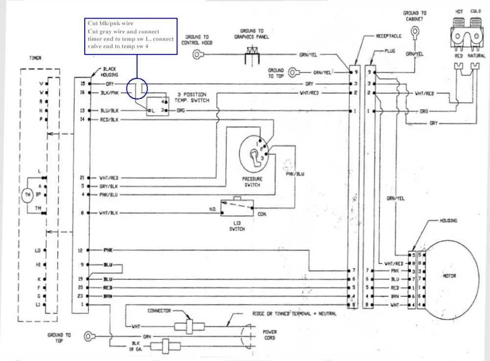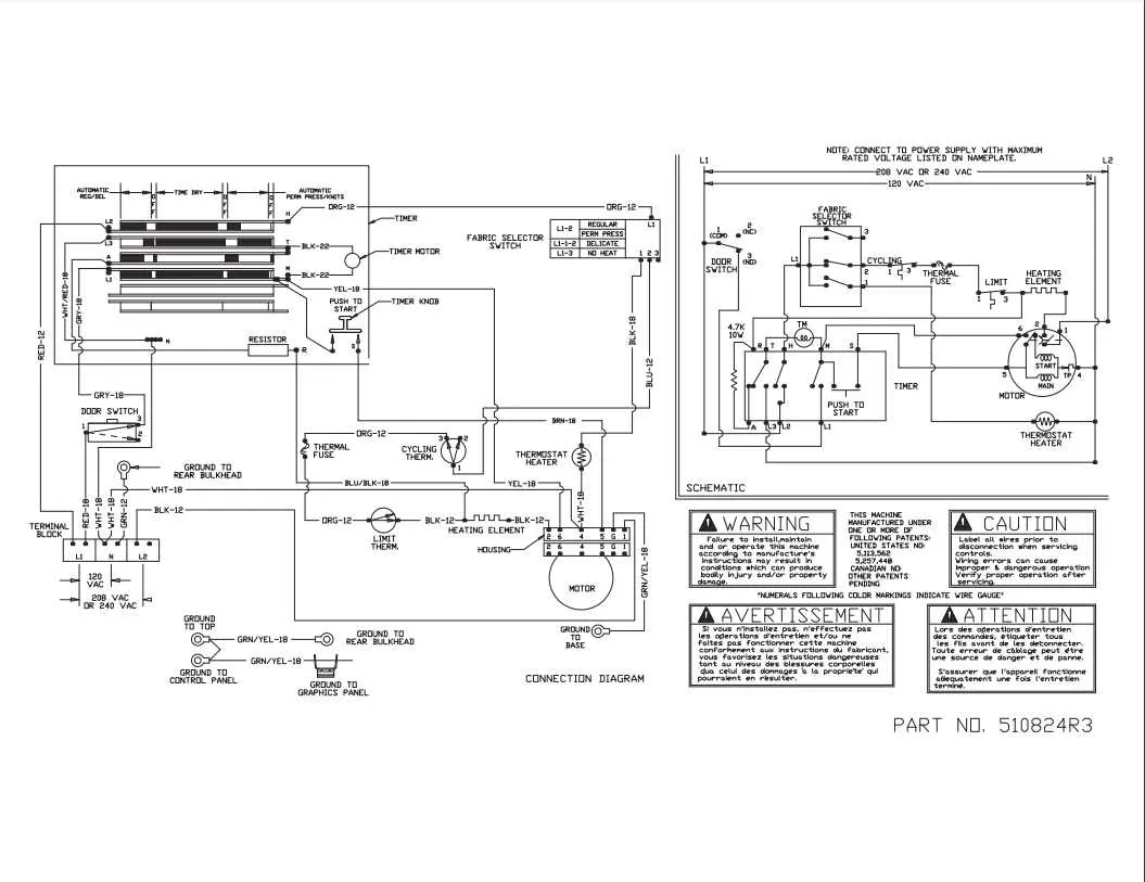
To ensure a proper connection and safe operation of your appliance, it’s crucial to follow the specific circuit configuration. Identify the key components that interact with the main power source, including terminals and connectors for both heating and motor systems. Each terminal has a designated function, which must be wired correctly to avoid malfunctions.
First, check the power source voltage to match it with the appliance’s requirements. A mismatch can result in the appliance failing to work or damaging internal components. Verify all connections are secure, using wire nuts or terminal blocks as appropriate to prevent accidental disconnections during use.
Next, pay attention to the grounding system. Grounding provides safety from electrical faults. Ensure the ground wire is connected to the designated point, preventing potential electric shocks. If your model includes a neutral terminal, make sure it’s correctly connected to the proper neutral wire coming from the electrical panel.
Lastly, review the schematics provided by the manufacturer. These offer step-by-step instructions and clarify which wires connect to specific parts like the motor, thermostat, and heating element. It is essential to follow the sequence outlined to maintain the appliance’s efficiency and safety.
Electrical Connection Guide for Laundry Appliance

Ensure proper connection of the terminals to avoid malfunction and ensure safe operation. Start by identifying the power inlet connections, which include the main live wire, neutral, and ground. Make sure the ground wire is securely connected to the appliance’s frame, and the live and neutral wires are placed in their corresponding terminals. Refer to the manufacturer’s manual for exact specifications on wire gauge and power requirements.
Check the control board for any visible signs of wear or damage. If you’re replacing or rewiring, ensure that all connectors are firmly inserted into the board. The heating element should have a dedicated power line, usually marked for easy identification. Keep an eye out for any potential short circuits between the terminals to prevent damage to sensitive components.
When working with the motor, verify that the connection for the motor’s capacitor is correct. Improper connections here can lead to failure in operation. Always inspect the wiring to the motor windings to avoid unintentional disconnections or fraying, which could cause power interruptions or safety hazards.
After the appliance is wired, run a continuity test using a multimeter to check that there are no broken or loose connections. It’s critical to ensure that all connections are securely locked in place before reconnecting the appliance to the power source.
Lastly, always adhere to local codes and standards when handling electrical components. If unsure about any steps or configurations, consult a certified technician for guidance.
How to Read and Interpret an Appliance’s Electrical Schematic
Begin by identifying key components such as the power supply, heating elements, and control switches. These parts will be central to the operation of the machine and typically feature in the schematic layout. Pay attention to the connections marked with standard symbols indicating live, neutral, and ground wires.
- Power Supply: The electrical input is usually represented with a pair of lines – one for live (hot) and one for neutral. Locate these at the top of the diagram for easy identification.
- Heating Element: This component is generally shown with a zigzag line. It connects directly to the power supply and is crucial for generating the necessary heat.
- Control Switch: Look for symbols that represent mechanical or electronic switches. These will often control the flow of current to the heating element or motor.
Next, trace the paths between these components. Each line on the schematic represents an electrical path, while different styles of lines (solid, dashed) may indicate varying voltage levels or signal types. Be sure to cross-reference with component labels, which should provide voltage and amperage information.
- Solid Lines: Usually signify high-voltage current flow to major parts like the heating system.
- Dashed Lines: Typically represent lower-voltage control circuits or connections that are controlled by sensors or the user interface.
Interpret any symbols that refer to safety features such as fuses or thermal cutoffs. These are often represented with a square or circle symbol, and will protect the machine from overheating or electrical faults.
- Start from the power source and trace each connection in sequence.
- Identify how current flows through the system during different operating phases, such as heating or cooling cycles.
- Check for any junction points where multiple paths meet. These are often control points where the user can alter machine behavior.
Finally, use the wire color codes for verification. These can be found in the diagram’s legend or within a service manual and should match the physical wires inside the unit.
Identifying Common Electrical Issues in Laundry Machines

Start by checking the power supply to ensure the unit is receiving the correct voltage. Use a multimeter to measure across the terminals of the power cord. If the voltage is incorrect, inspect the connection to the main power source or check the circuit breaker for any tripped fuses.
Examine the terminal block for any signs of overheating or burn marks. This could indicate a loose connection or a faulty terminal, which can cause intermittent power loss. Tighten any loose connections, but avoid overtightening, which may damage the terminals.
If the machine does not start, inspect the start switch for continuity using a multimeter. A failed switch can prevent the unit from powering on even if the electrical connections are intact. Replace it if necessary.
Check the door switch for proper functionality. A malfunctioning door switch can prevent the motor from running. Test the switch for continuity with a multimeter while the door is closed. If it fails the continuity test, replace it to ensure proper operation.
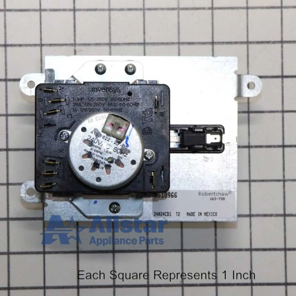
Inspect the timer mechanism for any signs of wear. A faulty timer may not engage the correct cycle, leading to operational problems. Test the timer for continuity and replace it if the connections appear damaged or if it does not cycle properly.
Finally, inspect the motor connections. A failing motor can sometimes be traced to faulty wiring or poor electrical contact within the motor circuit. If the motor does not respond to power, check the connections and motor relay for damage, and replace any faulty components.
Step-by-Step Guide to Repairing Dryer Electrical Connections
Ensure the appliance is unplugged before starting the repair. Safety is the top priority, and turning off the power prevents accidents during the process.
1. Access the Interior: Open the access panel or remove the back cover. Locate the terminal block or the area where the electrical connections are housed.
2. Inspect for Burnt or Damaged Wires: Look for signs of wear or burns. If any wire is frayed, broken, or showing visible damage, replace it immediately. Use a multimeter to test for continuity to confirm any faulty connections.
3. Check the Connection Points: Ensure each wire is securely connected to its respective terminal. Tighten any loose connections using a screwdriver. If a terminal is corroded, clean it using a wire brush to ensure good contact.
4. Replace Faulty Components: If any connectors, terminals, or wires are damaged beyond repair, replace them with components that are the correct specifications for your model. This ensures proper voltage handling and reduces the risk of further electrical problems.
5. Reconnect the Wires: Once the necessary repairs are made, carefully reattach each wire to its corresponding terminal. Double-check the wire placement according to the appliance’s model guide to avoid incorrect connections.
6. Test the Connections: After securing the wires, reconnect the appliance to power. Run a short cycle to verify proper functionality. Use a multimeter to ensure that the voltage readings are correct at each terminal point.
7. Close the Panel: Once everything is confirmed to be functioning correctly, replace the back cover or panel. Ensure it is securely fastened to prevent any loose parts from causing issues during future use.