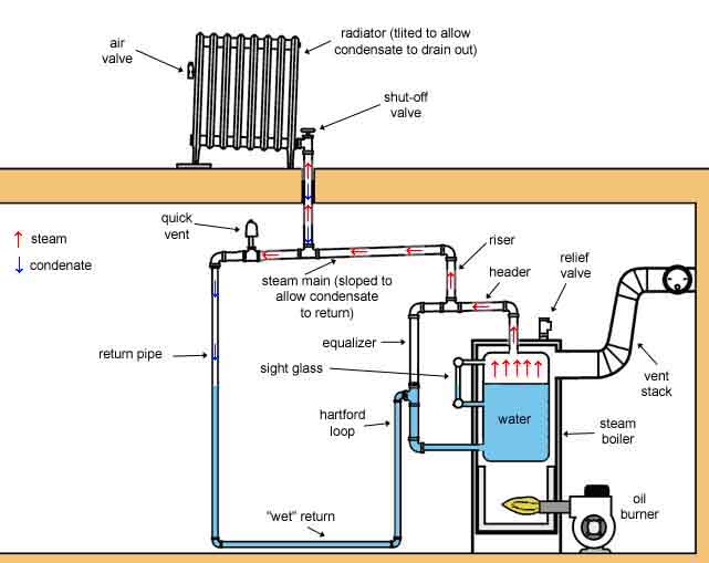
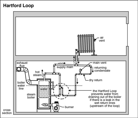
The primary component of a Hartford loop diagram is the location of a Hartford loop top and its distance from the boiler water top.
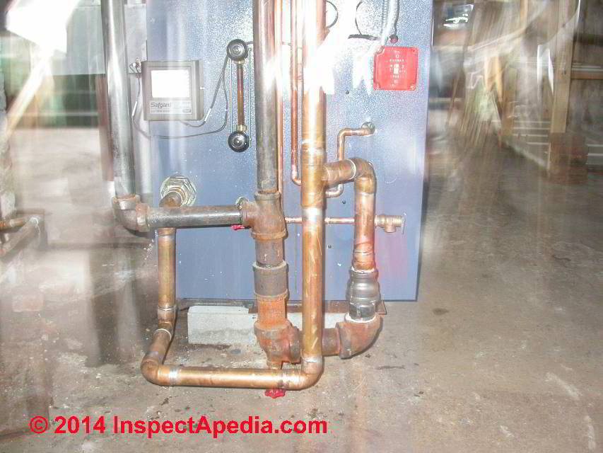
Standard Hartford loop. Photo credit: Dan Holohan The Hartford Loop isn’t just for steam jobs in Connecticut. It has a grand history and it has saved a lot of lives.
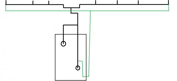
It’s one. Hartford loop piping schematic for a steam boiler – adapted from ITT’s The Steam Book – (C) . This diagram of a typical DWV system is called a plumbing tree.
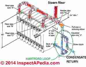
Hartford loop piping schematic for a steam boiler – adapted from ITT’s The Steam Book – (C) . This diagram of a typical DWV system is called a plumbing tree.
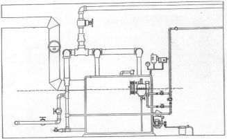
Photo credit: Dan Holohan The Hartford Loop isn’t just for steam jobs in Connecticut. It has a grand history and it has saved a lot of lives.
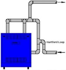
It’s one.Hartford Loop— Actually two loops, this system of piping acts as a safety device to prevent the water from draining out of the boiler if a leak develops in return piping. First loop surrounds boiler; second is the balance of the system.
Heating Unit— Convectors, cast iron radiators, wall-fin . The primary component of a Hartford loop diagram is the location of a Hartford loop top and its distance from the boiler water top.
Standard Hartford loop diagrams generally place the top of the loop 2 inches below the steam boiler’s water line. A Hartford Loop is an arrangement of piping between a steam boiler’s header and its gravity-return piping.
The end of the header drops vertically below the boiler’s water line and connects into the . Looking for hartford loop piping diagram for steam boiler – Answered by a verified Plumber We use cookies to give you the best possible experience on our website.
By continuing to use this site you consent to the use of cookies on your device as described . loop should be 12″ above the spa level, as close as possible to the spa.
See Diagram 2. To install the blower below water level, or if the blower air line drops below the bottom of the spa, use the Hartford Loop plumbing configuration (see Diagram 3) to prevent the air line from filling with water. Plumb a 1/2 lb.
U.L. listed check valve as shown.What you should know about the Hartford Loop and Gifford LoopHartford Loop Assembly,
