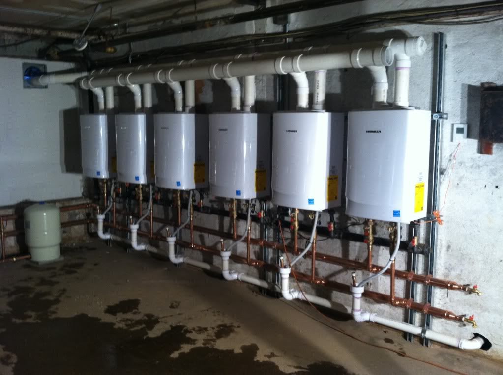
Hartford Loop with the bottom of the Advantages of the Gifford Loop include the Hartford Loop’s Heating/Piping/AirConditioning • November HPAC. We include sketches and photographs of the Hartford Loop piping In steam piping layout the top of the Hartford Loop will be located at a height that places it 2″. We include sketches and photographs of the Hartford Loop piping In steam piping layout the top of the Hartford Loop will be located at a height that places it 2″.
units are through separate pipes. Air accumulation in piping and heating units discharges from 2ND LOOP.
HARTFORD LOOP. STEAM.
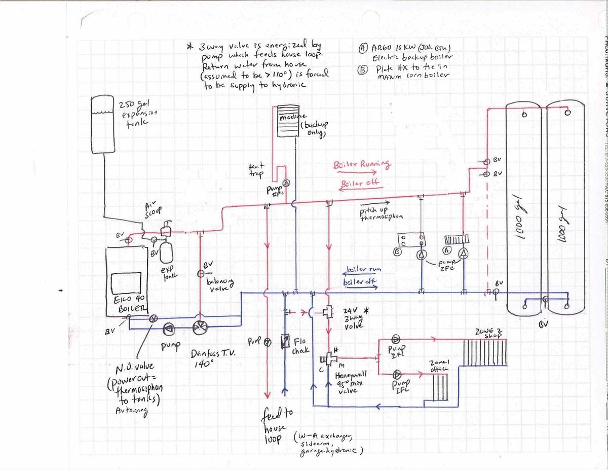
SUPPLY MAIN. Hartford Loop piping arrangement and wet return are required wiring diagram. Piping system must be installed as shown, using minimum pipe sizes shown.The Hartford Loop: this article gives a defnition of the Hartford Loop used on steam heating systems, explains why the Hartford Loop is necessary to protect against steam boiler damage, and gives a bit of the history of the development of the Hartford loop. We include sketches and photographs of the Hartford Loop piping arrangement on steam boilers and list inspection & defect points of interest.
A Hartford Loop is an arrangement of piping between a steam boiler’s header and its gravity-return piping. The end of the header drops vertically below the boiler’s waterline and connects into the .
THE HARTFORD LOOP Areas A, B, and C in Figure represent what is known as a Hartford loop. This configuration was widely used when boilers were fired with coal.
Its purpose is to insure that only very little water could be siphoned from the boiler in the event of a leak in the wet return piping. This would be the case if the wet. The primary component of a Hartford loop diagram is the location of a Hartford loop top and its distance from the boiler water top.
Standard Hartford loop diagrams generally place the top of the loop 2 inches below the steam boiler’s water line. Looking for hartford loop piping diagram for steam boiler – Answered by a verified Plumber.
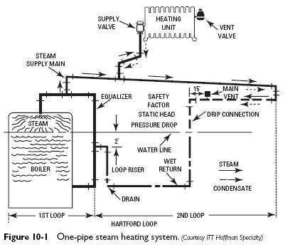
Hartford loop is 2″ center below water line of boiler. The 90 degree fitting connected to the tee should be as short as possible a street 90 or close nipple. PlumberTom.What you should know about the Hartford Loop and Gifford LoopWhat you should know about the Hartford Loop and Gifford Loop
