Teledyne Hastings Seven Things You Should Consider Before Selecting a Vacuum Gauge Webinar Recording. Teledyne Hastings Seven Things You Should Consider Before Selecting a Vacuum Gauge Webinar Recording.

Hastings VT-Series Vacuum Gauges are the circuit is attached to the rear of the direct Hastings Vacuum Controllers, CVT series are . Selection Chart. Consult Teledyne Hastings Instruments’s IGE-3 brochure on DirectIndustry.
Chart Typical gauge tube ordering/options number: System Connection. Consult Teledyne Hastings Instruments’s HPM 4/6 portable, dual range vacuum gauge brochure on DirectIndustry.
P.O. Box Hampton, VA Selection Chart Note: Sensors sold separately.
Sensors to 1 Torr to 20 Torr Connection DV-6M DV-4D 1/8″ NPT DVT/DCVT digital vacuum gauge/ controller.Page 5 of 19 2 Installation and Wiring Installation The POWER OD model enclosure is designated for panel mounting in a 1/8 DIN cutout. The cutout dimensions are shown below.
Panel mount ing the POWERPOD To mount the POWER OD to . Hastings HVAC is a global manufacturer of energy-efficient commercial & industrial HVAC systems for heating, ventilation and air conditioning.
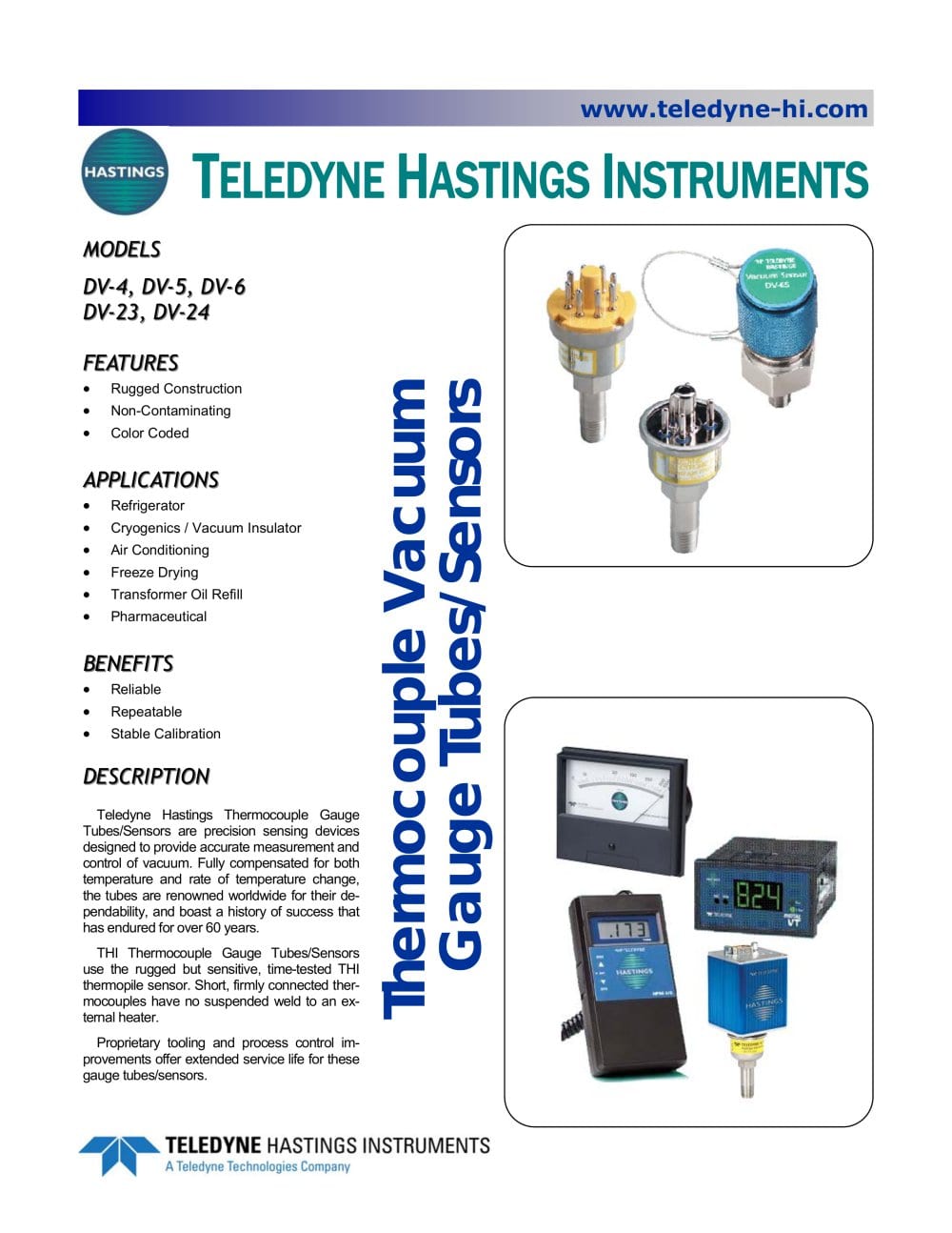
Hastings HVAC is a global manufacturer of energy-efficient commercial & industrial HVAC systems for heating, ventilation and air conditioning. The Teledyne Hastings’ DV-4 Series thermocouple vacuum gauge tube/sensor can be paired with a variety of meters or controllers in the DV series to provide reliable, cost effective measurements in a variety of applications.
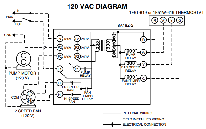
HASTING HVAC WIRING DIAGRAM (), NPN. Order from Heritage Parts the leading online provider of OEM commercial kitchen replacement parts. Most parts ship same day.

If optional motorized dampers are used, connect electrical wires supplied (in factory furnished conduit) with unit to damper motor as shown on electrical wiring diagram. Adjust linkage so that damper will close when blower switch in remote control panel is in “off” position.DAVC – Teledyne Hastings Instruments – PDF Catalogs | Technical Documentation | BrochureHASTINGS IHR SERIES INSTALLATION AND SERVICE MANUAL Pdf Download.
