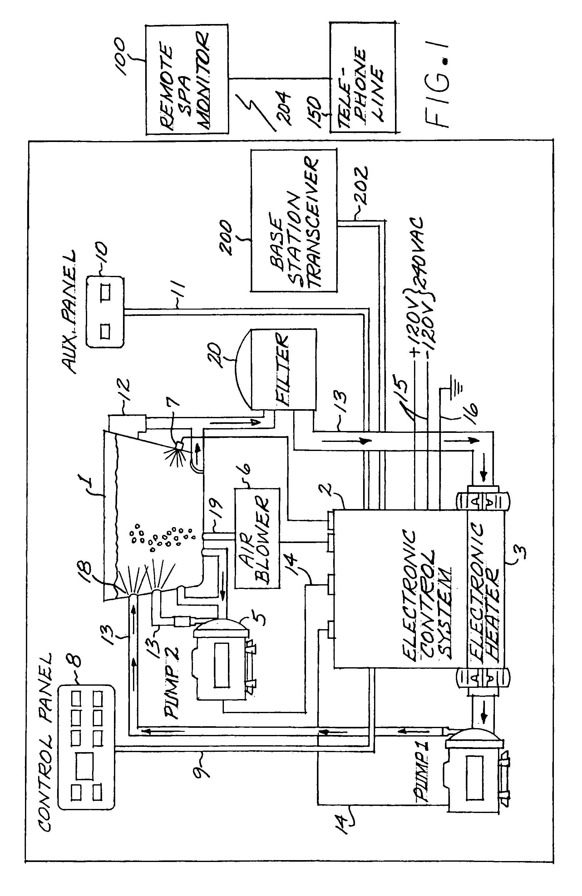
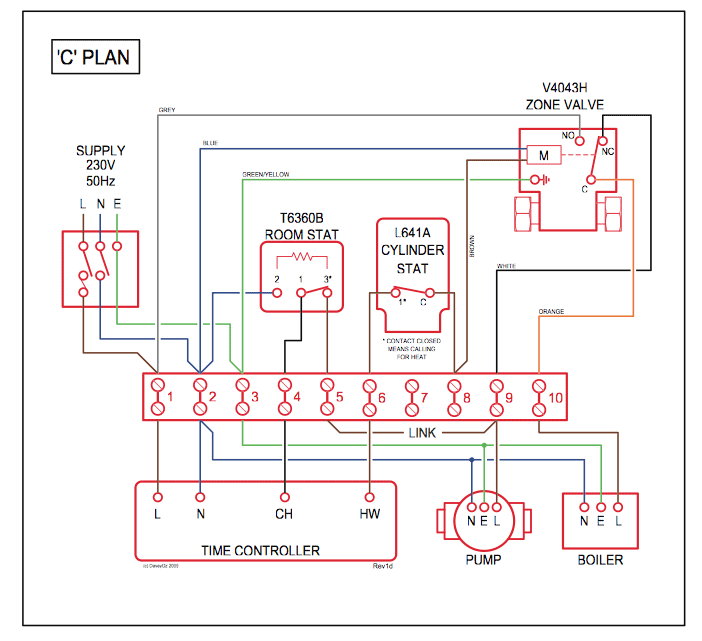
Before attempting to install the Pro Logic system, check that the following Hayward Variable Speed Filter Pump: Refer to the diagram below for proper low . Wiring Hayward GAS Pool Heaters for Parallel Operation Manual · File Size KB .
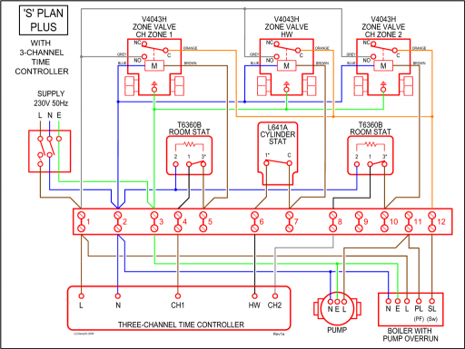
ProLogic Installation Manual Addendum (Prior to Oct 08) · File Size How to Wire V Equipment to the Hayward Pro Logic. to the Pro Logic. The wiring diagram should describe where to connect the ground and hot lines.
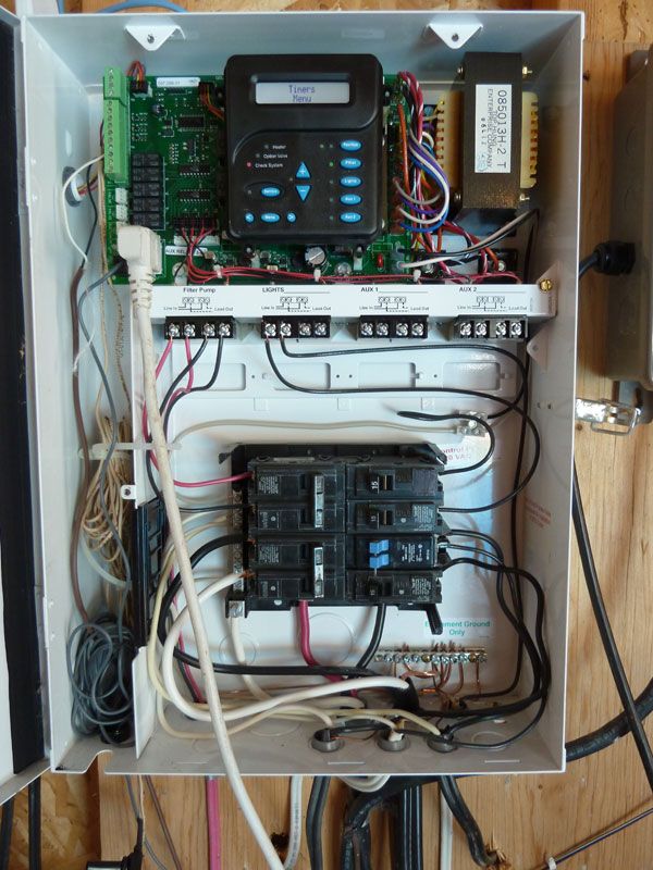
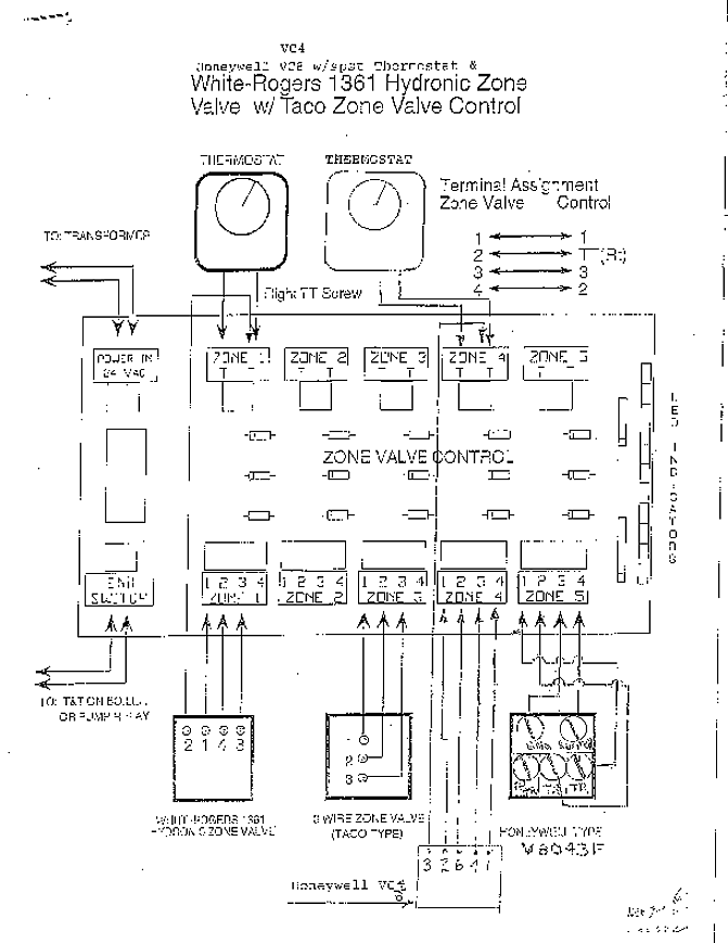
Hayward Pro Logic Manual Online: Low Voltage Wiring. Valve Actuators The Pro Logic can control up to four (PS-4/8) or eight (PS) 24V automatic valve.
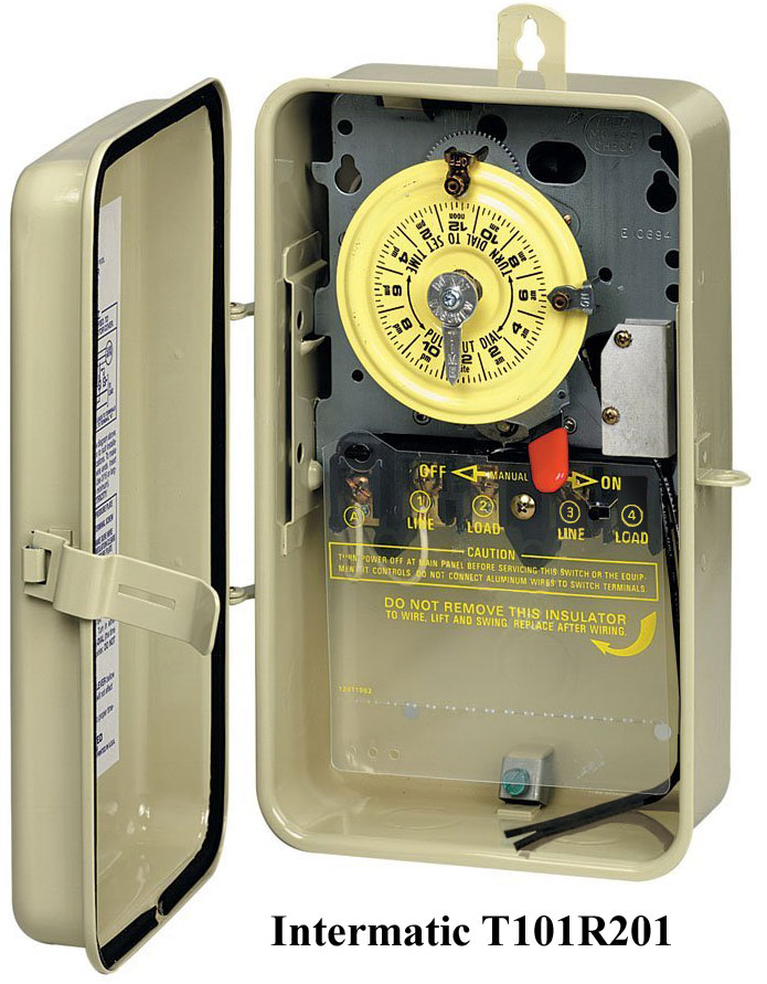
Pro Logic. Automation and Chlorination.

Installation Manual. D RevJ.
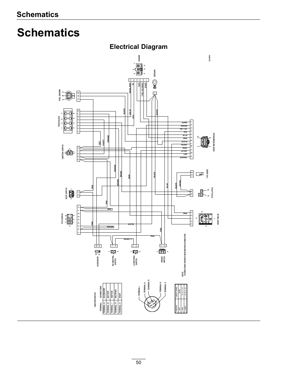
PL- PS-4 Valves (use standard Hayward, Pentair/Compool, or Jandy valves). Additional .. Also refer to the Base Station manual and the diagram on page View and Download Hayward Pro Logic® installation manual online. Model: Pro Logic Installation Addendum Oct 08 or later. Pro Logic® pdf manual download.
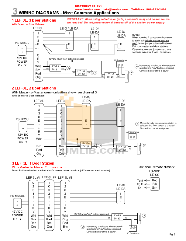
Refer to the diagram below for proper input wiring to the VSP. Wiring from. the V breaker .
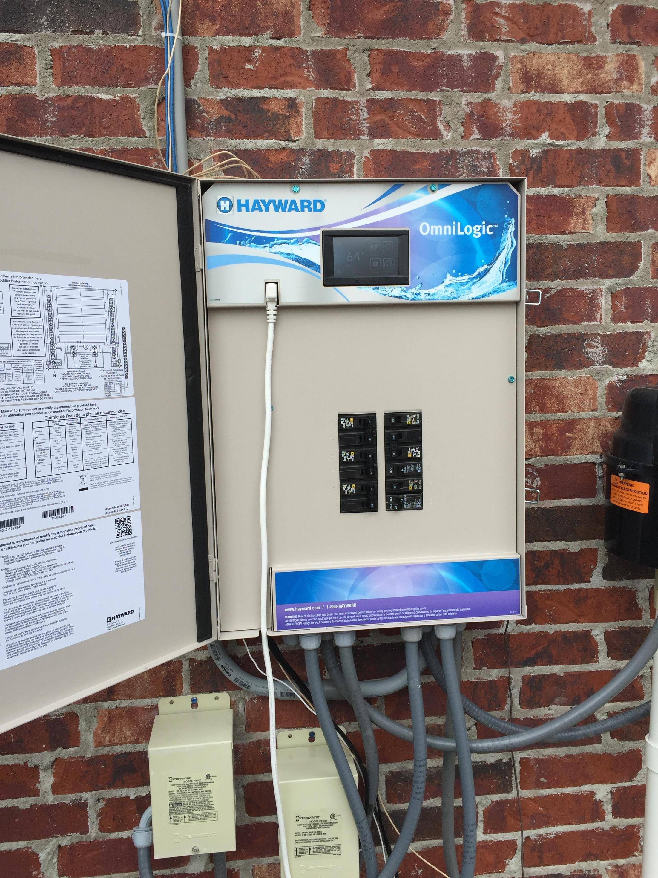
Replacement Parts for the Pro Logic Replacement Parts by Hayward. Mar 18, · Create your own automation and chlorination system with Pro Logic. Whether you have a basic pool or an extensive backyard paradise, Pro Logic always offers the right level of control for your.
Hayward Pool Products View FAQs. Contact Hayward Support We are here to help with all of your Hayward Pool Products.
Get support by contacting us online Contact Support. Amazon Echo Dot Offer.
VS OMNI PUMPS WITH SMART POOL CONTROL. The Pro Logic can control up to 2 Hayward TriStar VSPs and 8 EcoStar VSPs.
Refer to the diagram below for proper input wiring to the VSP. Wiring from the V breaker must connect through the Pro Logic’s Filter/Lights/Aux relay.How To Wire A 2-Speed V Motor to a Hayward Pro Logic System – schematron.orgManuals | Resources – Hayward Pool Products
