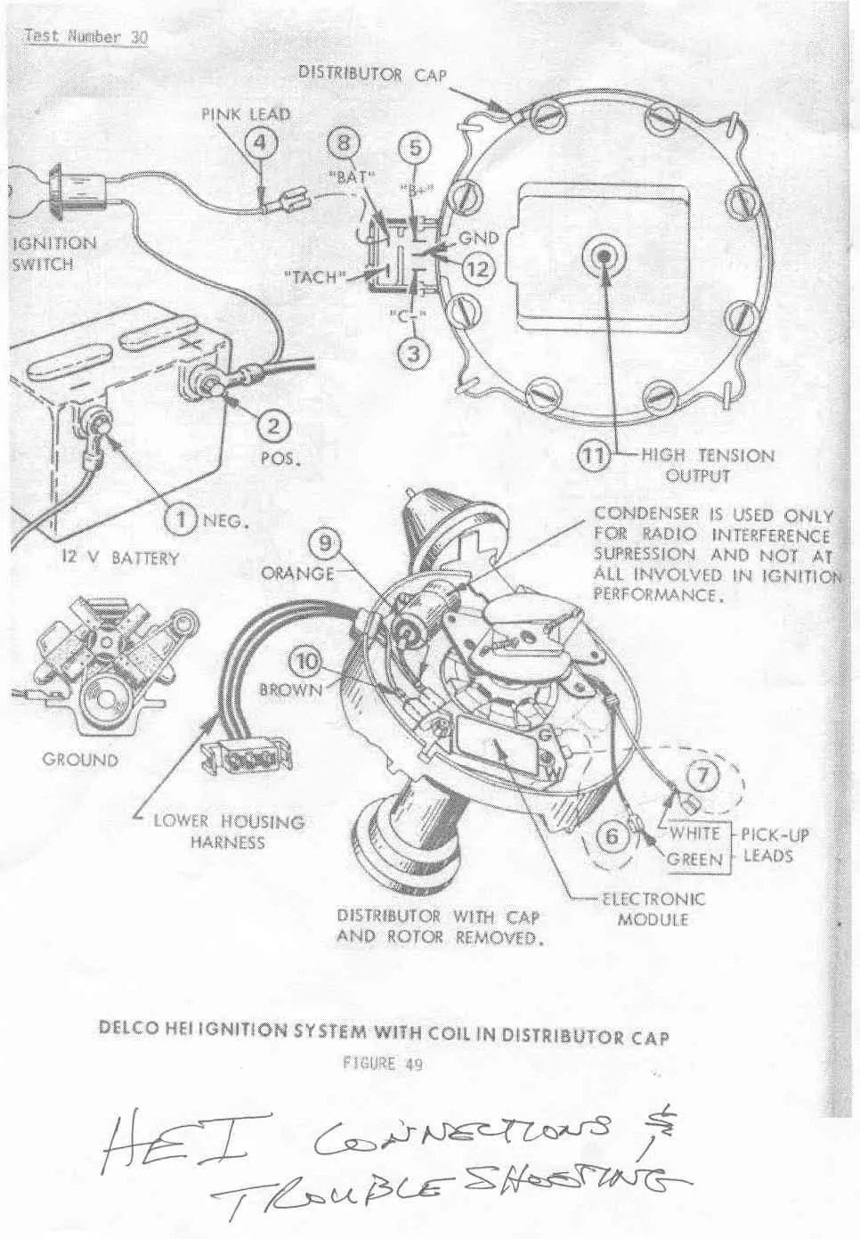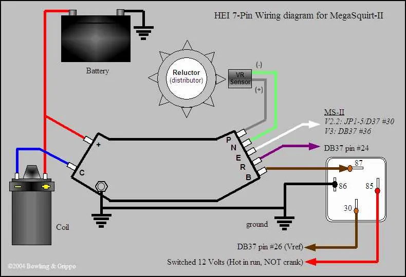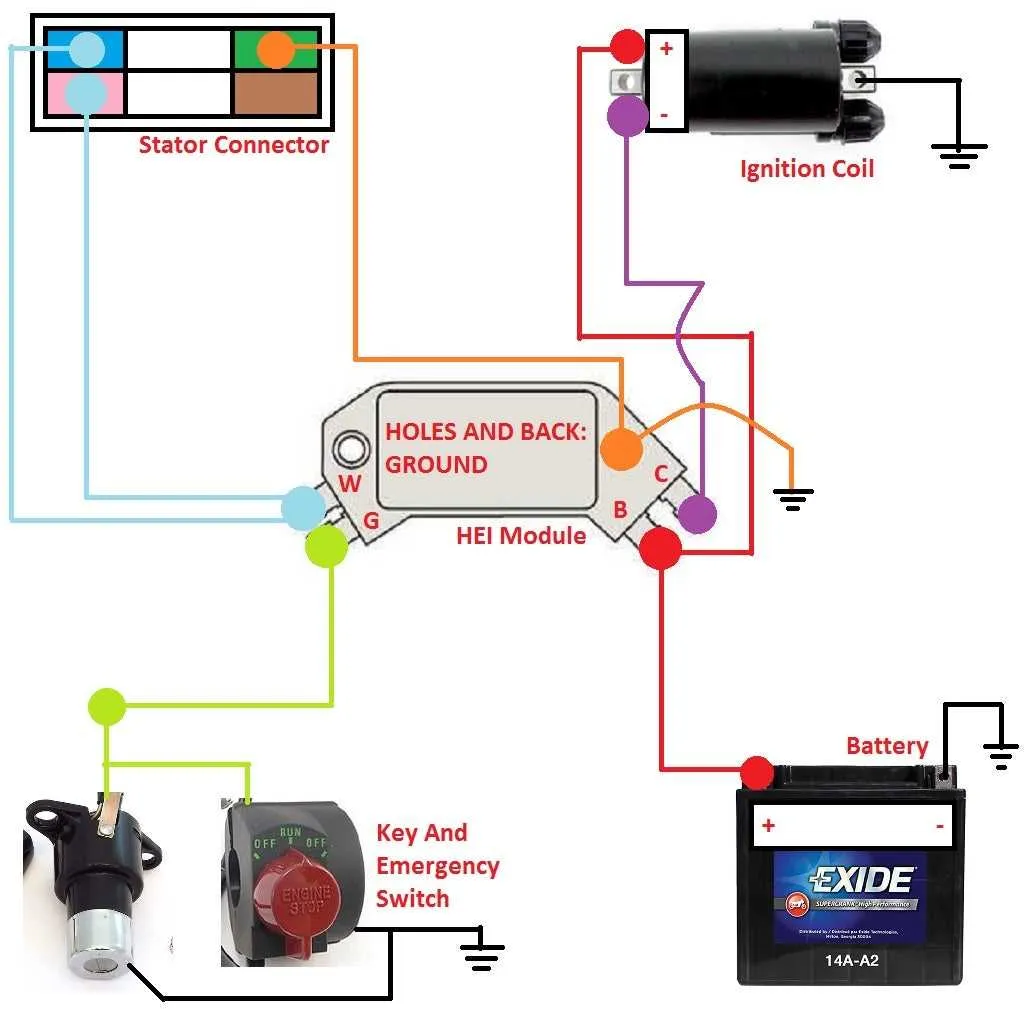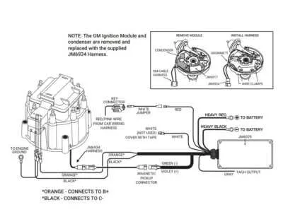
Connect the battery feed directly to a 12V ignition source that remains hot during crank and run cycles. Avoid using a ballast resistor or resistance wire–this setup requires full voltage to operate correctly and consistently.
Route the signal cable from the distributor to the module’s terminal labeled “B” (for battery). Ensure the wire gauge is sufficient to handle the current draw, typically 10–12 AWG for primary power leads.
Attach the tachometer lead, if used, to the “TACH” port on the module. If no tach is present, leave this pin unused. Improper grounding or signal interference on this line may cause erratic engine performance or starting issues.
Ground the module housing directly to the engine block using a dedicated ground strap. Poor grounding is a common failure point and may lead to inconsistent spark or total loss of output under load.
Use shielded wiring or twisted pairs for the pickup coil leads to reduce electromagnetic interference. These wires connect to the internal sensor and must remain isolated from high-voltage lines to maintain a clean trigger signal.
HEI Ignition Wiring Diagram
Connect the battery feed directly to the terminal marked “BATT” using a 12-gauge wire to ensure proper voltage delivery under load. Avoid using resistance wire or stock harness leads, as voltage drop can cause misfire at high RPM.
- Run a dedicated 12V source from the fuse box or ignition switch to the power input.
- Use a separate ground wire from the housing to the engine block to ensure consistent grounding.
- The “TACH” pin is optional and should only be used for connecting a tachometer. Leave unconnected if unused.
- For vehicles with factory points systems, bypass the ballast resistor completely when converting.
If integrating into an older harness, trace the pink resistance wire and replace it entirely with a full-voltage line. Secure all joints with solder or weatherproof connectors to prevent voltage fluctuations due to corrosion or vibration.
- Identify the keyed switch output wire.
- Use a relay if routing power from a low-amperage circuit.
- Fuse the circuit with a 20A inline fuse within 12 inches of the power source.
Ensure the distributor’s base is clean and torqued correctly; poor mechanical connection can mimic electrical faults.
How to Wire an HEI Distributor to a 12V Ignition Source

Connect a 12-gauge wire from the distributor’s BAT terminal directly to a switched 12V supply. Avoid using a ballast resistor or resistance wire, as these reduce voltage and compromise performance.
Use the ignition switch output that delivers full battery voltage during both crank and run positions. Verify this with a multimeter–ensure a steady 12–14V when the key is turned.
Secure all connections with crimped or soldered terminals and heat shrink tubing. Loose or corroded joints can cause misfires or starting issues.
If retrofitting a vehicle originally designed for points-style systems, bypass any inline resistor in the existing circuit. Route the new power feed from a relay triggered by the ignition switch to ensure consistent current flow.
Ground the distributor housing to the engine block using a clean, direct strap. Poor grounding can result in erratic spark or module failure.
Identifying and Connecting Tach and Battery Terminals on HEI Cap

Connect the power supply to the “BAT” terminal using a 12-gauge wire from a switched 12V source. This ensures consistent voltage delivery during engine operation. Do not use a resistor wire or ballast–full voltage is required for optimal performance.
Locate the “TACH” post adjacent to the power terminal. It’s typically marked on the plastic housing and often unused unless a tachometer is installed. To hook up a tach, run a dedicated wire from this terminal directly to the tachometer’s signal input. Do not splice this wire with any other circuits.
Verify terminal identification before connection. “BAT” is typically on the left when viewing the module from the front with the terminals facing you, and “TACH” on the right. Always confirm markings stamped on the cap to avoid reversed polarity or misconnection.
Use push-on connectors that fit tightly over the spade terminals. Loose fittings cause intermittent performance issues and possible arcing. Crimp terminals securely and apply dielectric grease to prevent corrosion.
Troubleshooting No-Spark Issues in HEI Systems

Start by verifying the primary voltage supply: Measure battery voltage at the module’s input terminals; it must be stable and above 12 volts. If voltage is low or intermittent, check for corrosion or loose connections on the power feed and fuse links.
Inspect the coil ground and connections: A poor ground can prevent spark generation. Use a multimeter to ensure the ground wire has continuity to the chassis with less than 0.1 ohm resistance.
Check the distributor module signal output: Use an oscilloscope or test light on the module’s control wire to confirm pulse presence when cranking. Absence of pulses indicates a faulty control unit or trigger mechanism.
Test the pickup coil resistance: Measure coil resistance with an ohmmeter; typical values range between 500 and 1500 ohms. Open or shorted coils require replacement.
Examine all connectors for corrosion or damage: Clean terminals with electrical contact cleaner and reseat firmly. Loose pins or oxidized contacts often cause no-spark conditions.
Verify the condition and routing of signal wires: Ensure no cuts, abrasions, or pinched sections exist. Signal wires should be routed away from high-current cables to avoid interference.
Confirm proper timing and mechanical alignment: Misaligned reluctor or pickup can prevent pulse generation. Adjust gap settings between 0.010 to 0.020 inches for optimal sensor triggering.
Systematic elimination of power supply faults, signal interruptions, and sensor defects will restore spark functionality reliably.