ALL, Installation Instructions, Installation/Technical Support, Owner’s Manual Heil Resource Center for Heating & Air Conditioning Dealers & Contractors.
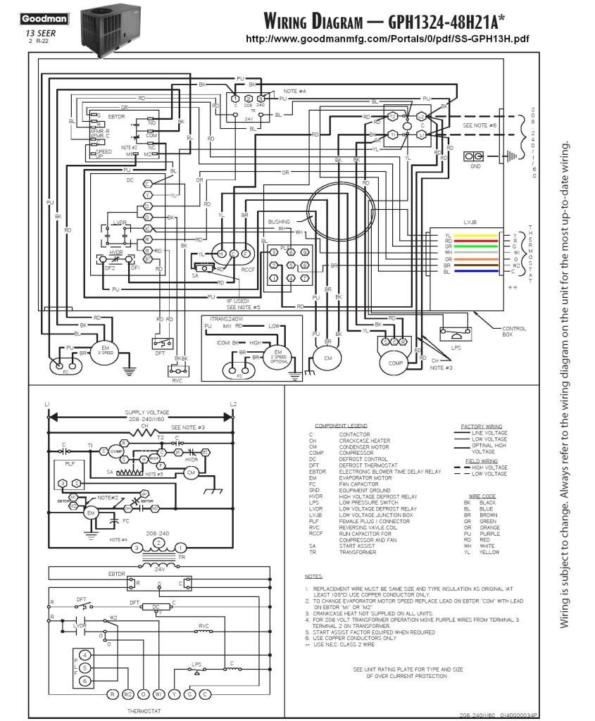
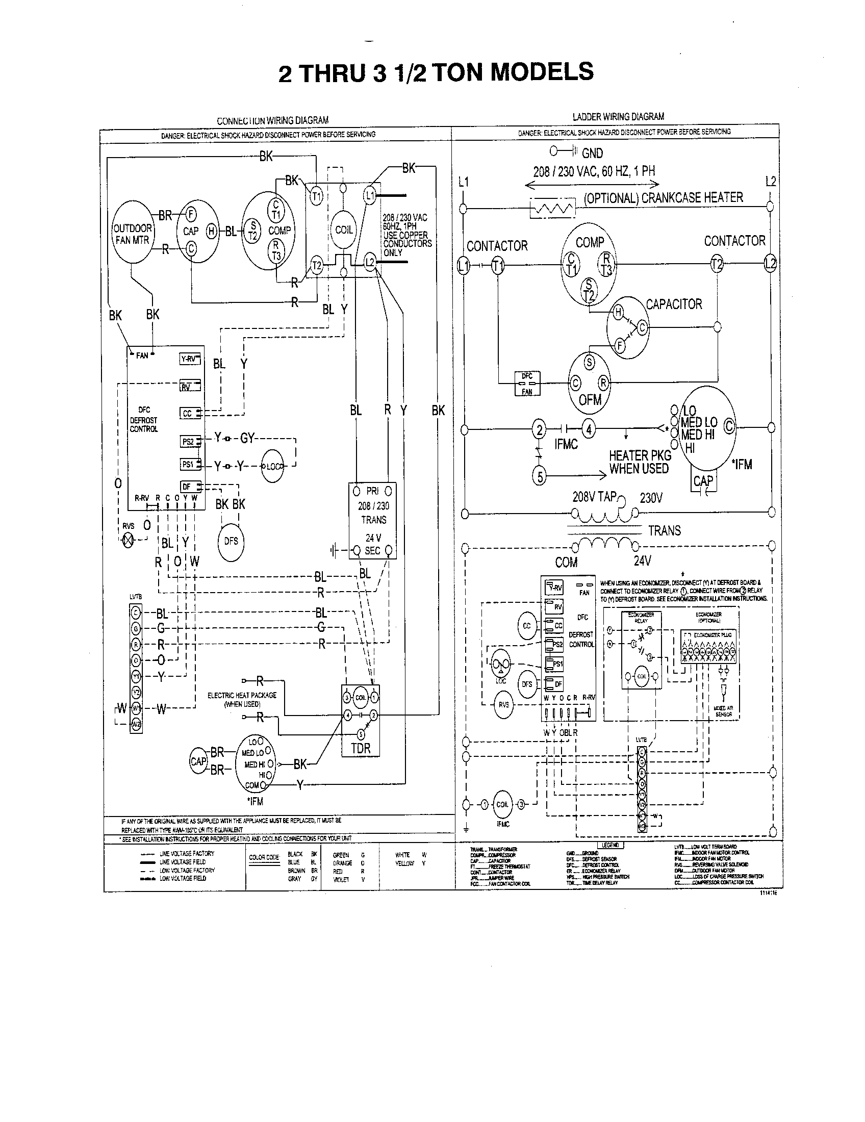
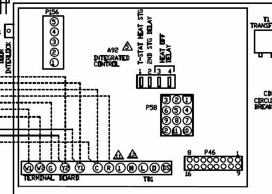
The orange wire coming out of the outside unit is for the reversing valve(controls the heat and cool mode of the ac) If its unhooked, it will be. Does anyone know where I can get a wiring diagram for a Heil CHVKB2 heat pump?
S/n is L I tried heil site but was just. Split System Heat Pump: N4H3. 4.
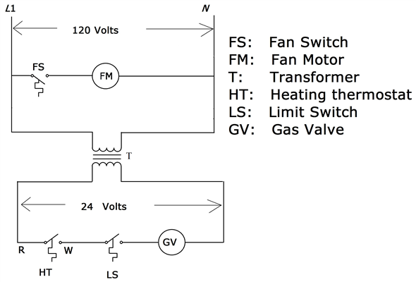
04 1. Symbols are electrical representation only. 2.
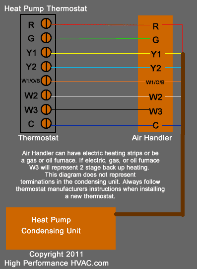
Compressor and fan motor furnished with. power requirement for heat pump condensing unit is.
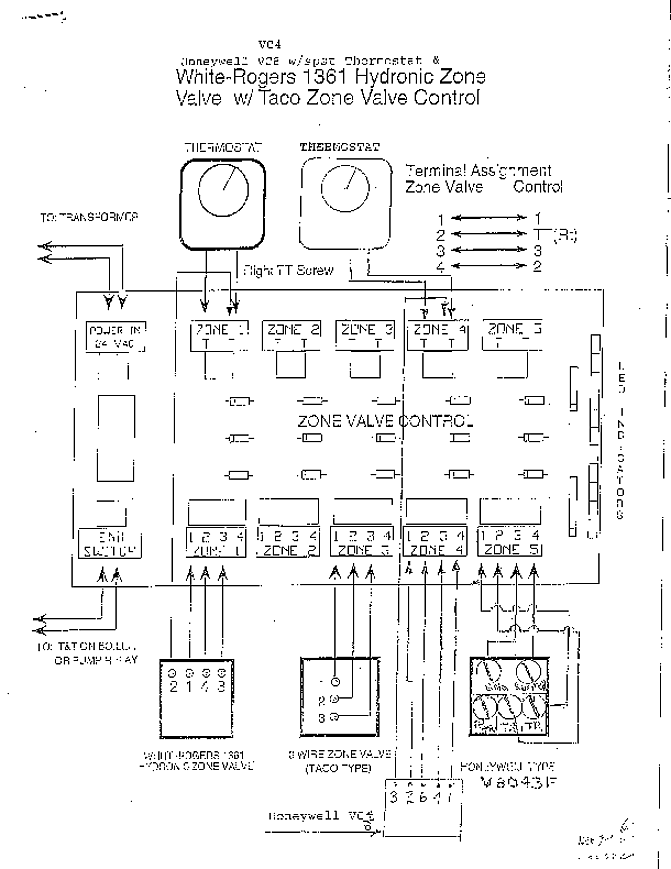
36 va (sealed). Supplied control transformer is 75 va.
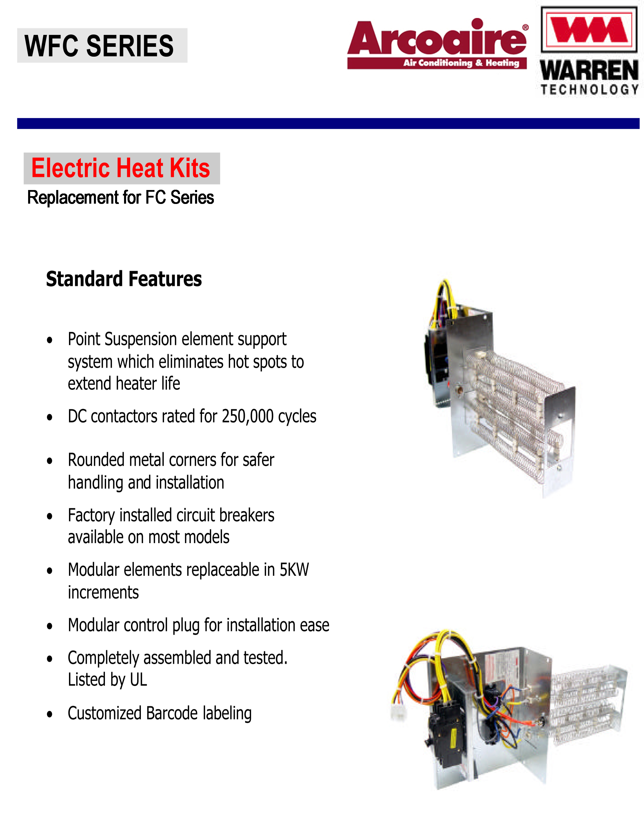
NOTES (Fig. 11). 1.
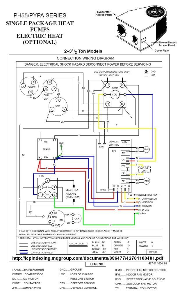
Factory wiring is in accordance.View and Download ICP PH55 Series installation instructions manual online. PH55 Series Heat Pump pdf manual download.
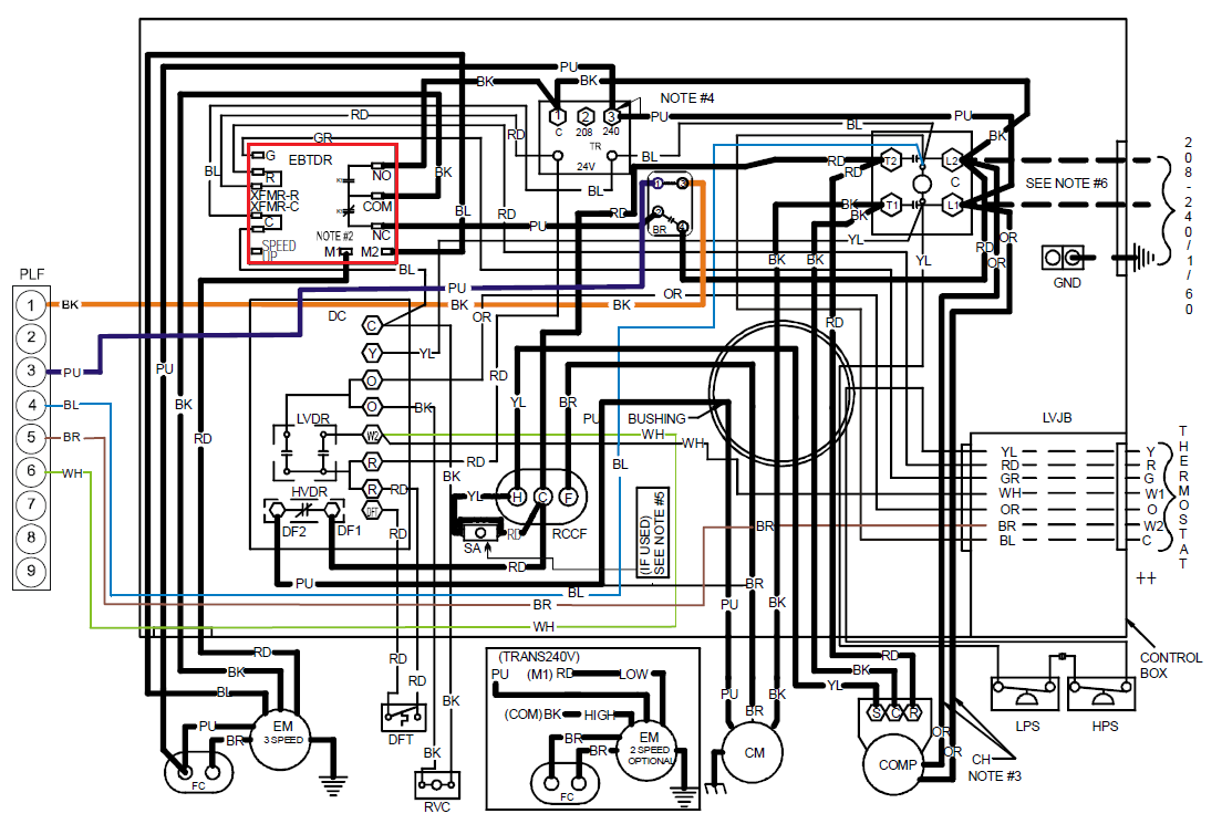
Also for: Pypa series. Wire Diagrams – Electric Heat Accessory DESCRIPTION: WIRING CODE_ REVISION_ AM[vlK & 15 KS! ELECTRIC [ 2£18/23_1V 5_,18 HEAT 1 PH,,J/’, i\N ELECTRICAL SHOCK HAZARD DISCONNECT POWER SUPPLIES.
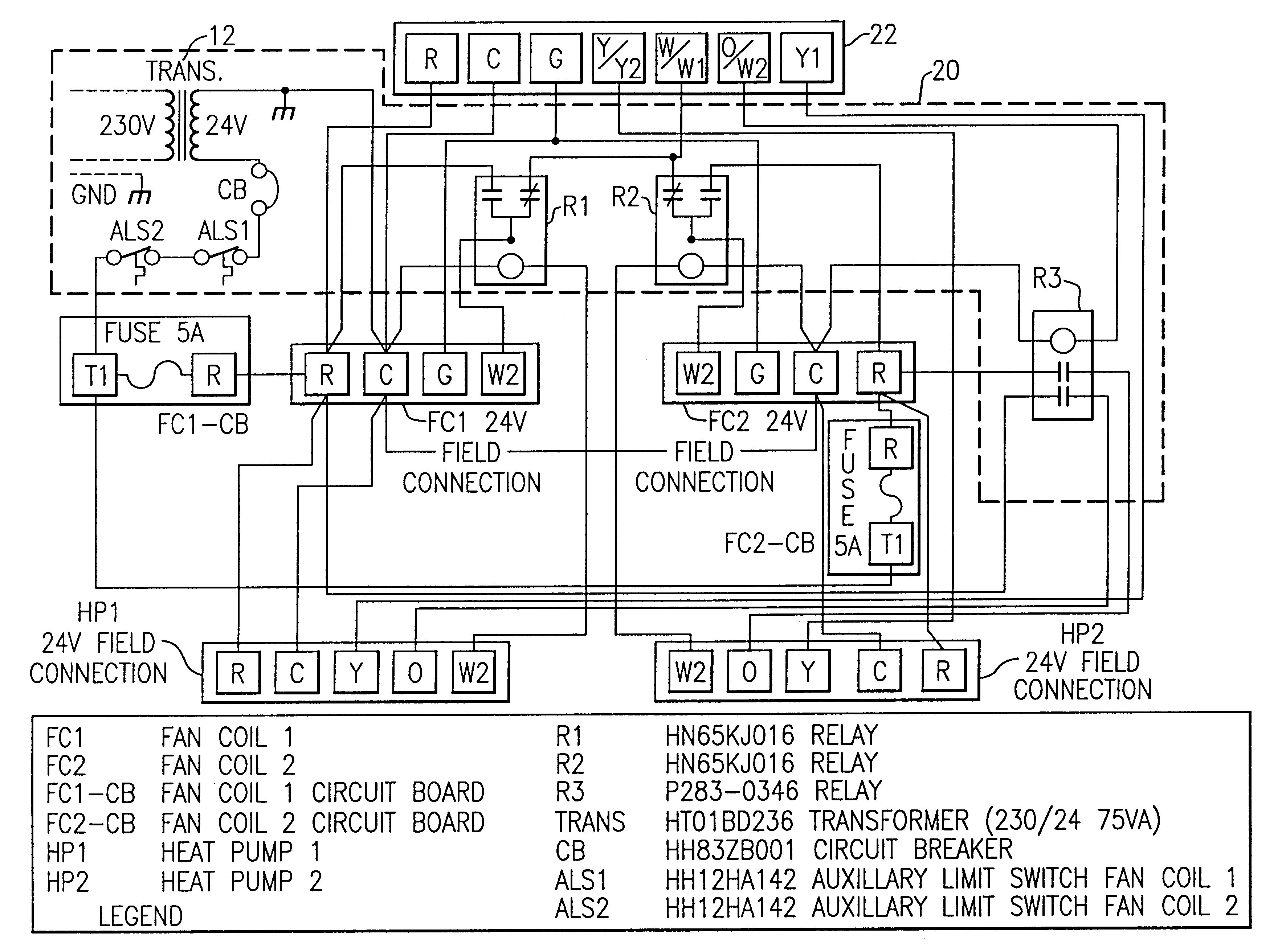
Heil furnace thermostat wiring diagram in addition carrier electric furnace model numbers in addition nordyne gas furnace wiring diagram along with carrier ac wiring diagram further tempstar wiring diagram further gas boiler sensor further bryant furnace bryant furnace wiring 0c90dd7f57efee28 as well as ducane heat pump control board wiring moreover suburban water heater thermostat. Need a wiring diagram for relays on a heil furnace model #NUGKAH02 – Answered by a verified HVAC Technician We use cookies to give you the best possible experience on our website.
By continuing to use this site you consent to the use of cookies on your device as described in our cookie policy unless you have disabled them. Jan 01, · Does anyone know where I can get a wiring diagram for a Heil CHVKB2 heat pump?
S/n is L I tried heil site but was just consumer crap. TECHNICAL SUPPORT MANUAL Split System Heat Pump: (C,H,T)2H3 4 04 02 R CHARGING CHART Find the required Subcooling Temperature on the unit Rating Plate.
Use the closest column on the chart below (5, 10, 15, or 20). Add or remove refrigerant until both the Liquid Line Temperature and Liquid Pressure agree with chart data.Arcoaire Heat Pump Wiring Diagram | Wiring LibraryICP PH55 SERIES INSTALLATION INSTRUCTIONS MANUAL Pdf Download.
