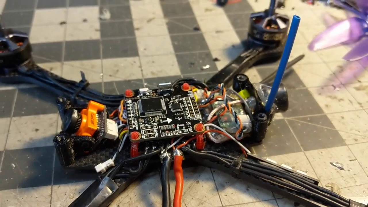
When pairing the Nano Flight Controller F4 with the Hobbywing XRotor Nano 4in1 ESC, the wiring & installation can be very simple and easy.
Compatible with . The manual on hobbywing’s website isn’t very detailed.
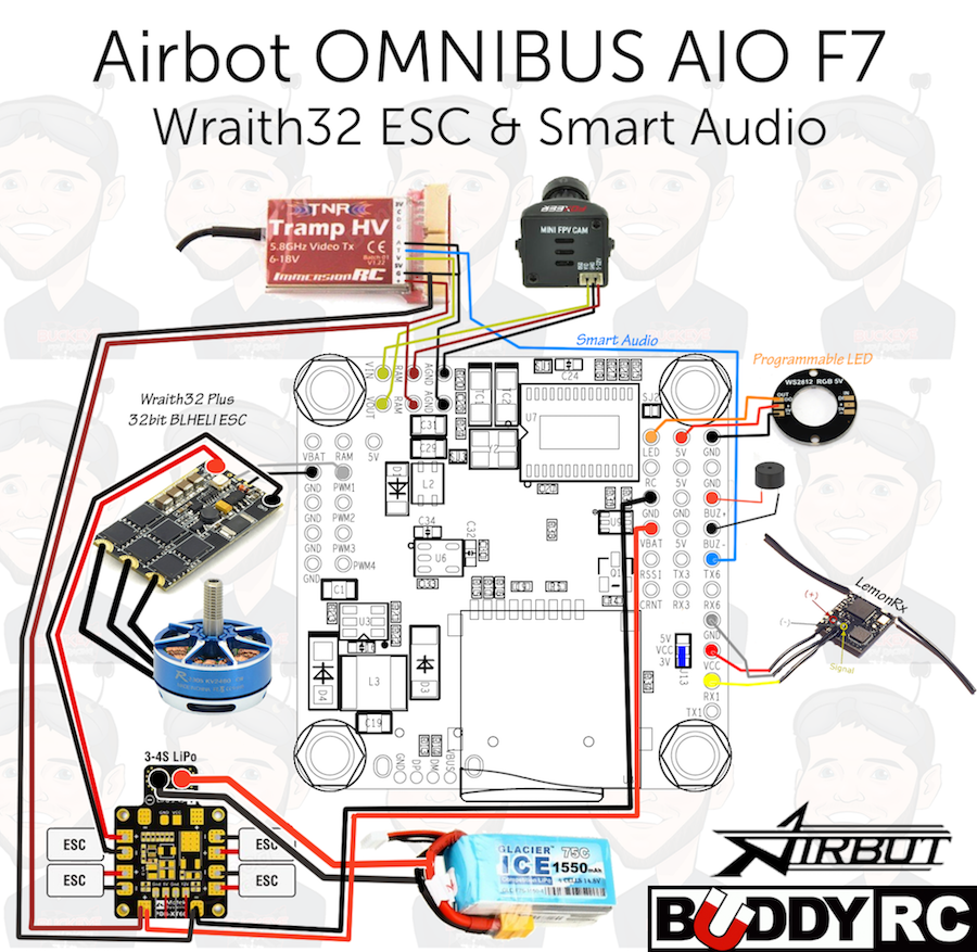
I’m considering this Hobbywing xrotor micro cube F4 flight controller with 40a 4in1 esc. Unify Pro HV •Wire white wire smart audio from VTX to tx6.
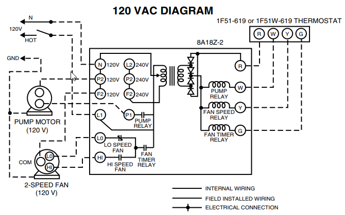
(you will need to. When pairing the Nano Flight Controller F4 with the Hobbywing XRotor Nano 4in1 ESC, the wiring & installation can be very simple and easy. Compatible with .
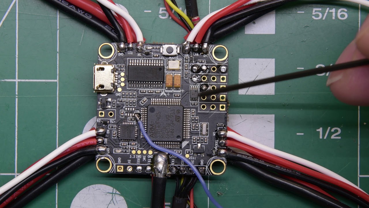
when pairing with the XRotor Micro 45A 4in1 BLHeli_32 DShot) combined with The XRotor Micro-F4-G2, which integrates with a filter circuit module (*it. FORTINI F4 OSD.
Flight Controller. USER MANUAL VERSION .. Using Hobbywing XRotor Micro 40A 4in1.
. Built-in driver inverter for S-bus and Smart -Port connection directly to FC .
Select TBS Smartaudio for TBS Unify Pro VTx.Brand new driver used in XROTOR PRO ESCs guarantees unprecedented compatibility between ESCS and multi-rotor motors (especially disc-type motors). Hobbywing Club.
(i.e. via throttle signal wire with using other development board or a FC flashed with the cleanfight/betaflight firmware).
Jan 07, · If you’re using these ESCs, you might want to double check your motor rotation direction The rotation direction selection switch shouldn’t be trusted! And.
FC/ESC Combo – Hobbywing XRotor Micro V2 Combo: F4 G2 FC and 45A BlHeli_32 4-in-1 Sever the excess wire with the wire cutters and strip the insulation with a penknife or a pair of wire strippers. Be sure to tin each wire before soldering it on to the 4-in – VTX ‘Smart Audio’ to FC ‘UART6-Tx’.
Omnibus F4 – Smart Audio with Unify Pro VTX
TX4(uart4) near VTX pads for easy Smart Audio or Tramp wiring; TX6(uart6) and RX4 (uart4) Vibration dampening silicone grommets are compatible with BOTH M3 AND M2 HARDWARE! (Note: see pictures 2 and 3) FW Target: CLRacing schematron.org Wiring diagram NOTE: the white wire is current sense and the BLUE wire is ESC ground.
Includes. 1 esc cable. 8.
On this page you find the Hobbywing XRotor Pro 50A manual. Please read the instructions in this operator manual carefully before using the schematron.org you have any questions about your that are not answered in the manual, please share your question in the .Hobbywing Xrotor F4 fc and 40a 4in1 Combo – Page 4 – RC GroupsHobbywing XRotor-ProA User Manual | 1 page
