masses of the charged lepton of the corresponding generation).

.. The solenoid is connected axially to SINDRUM II and has the same field strength as the Figure 6: Schematic representation of the proposed p~ channel for the. SINDRUM I would like to thank my colleagues on this work, including L. Han, R.
Holmes, J. europhysicsnews.
V o lu m e. 4. 2.

• n u m b e r. 4.

Eu ro p e an. U n io n .. consequence of the gap between gen- ..

solenoid. if the photon mass is not zero, the electromagnetic Schematic energy level diagram showing the injection of electrons and holes ..
University of Denmark – DTU Building OWNER’S MANUAL. DTU GEN2.

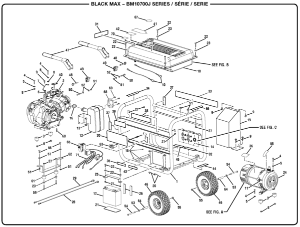
PARTS. NOTE: MANUAL including SPECIFICATIONS, subject to change without notice.

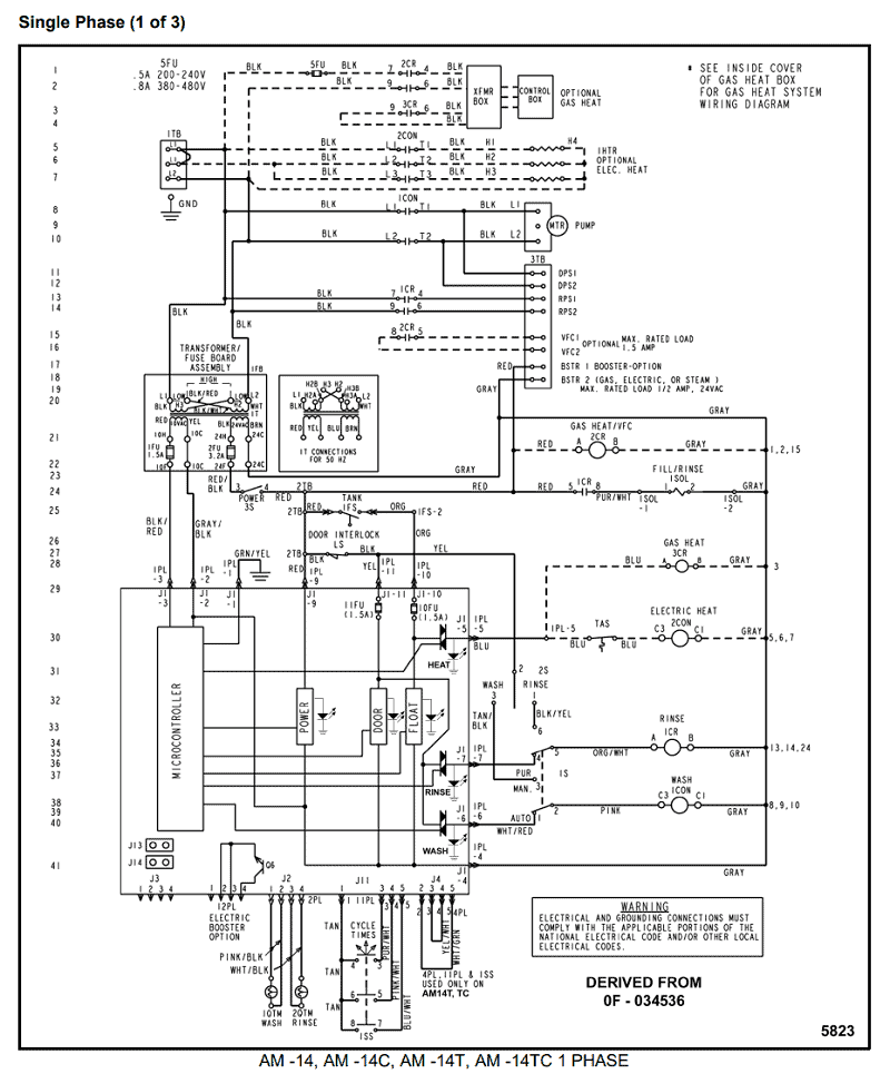
All ratings specified are based on. Figure The circuit diagram for the low-frequency noise measurement.

. Figure An illustration of the solenoid with a dielectric slab (e.g.

silicon wafer) on the . billion interconnected devices by as predicted by Cisco [2].

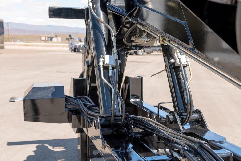
optical image sensing [6], ultrastable microwave signal generation [7], and much more. The Holmes DTU (Detachable Towing Unit) has been re-designed to decrease Fork Storage Holders; Air & Electrical Lines; Safety Chains; Passenger Side.Remote cable link solenoid can be used for throttle advance or shutdown requirements.
Ideal for applications with space restrictions, extremely hot environments or excessive vibration. Put the power of Woodward solenoids to work on your engines.

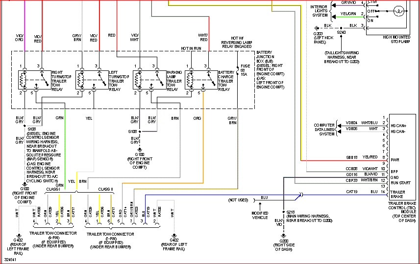
2 -Shift Cutout Switch 3 -Filter 4 -Ignition Coil B-Starting System 1 -Alternator 2 -Electric Choke (2 BBL Only) 3 -Ground Bolt 4 -Starter 5 -Circuit Breaker 6 -Starter Slave Solenoid C-Audio Warning System 1 -Water Temperature 2 -Drive Unit Oil Level (If Equipped) 3 -Oil Pressure Switch D-Instrumentation System 1 -Oil Pressure Sender 2 -Water. Dec 05, · Solenoid Wiring.
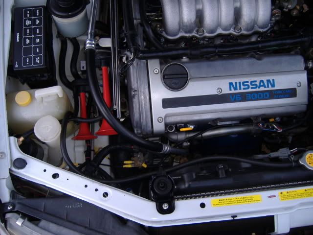
Does it matter what wires go where? I would hope you know how to wire, or find a wiring diagram, for that selenoid.
Gicon, Nov 28, #2. wls Senior Member.
from Mid-Michigan. Messages: I don’t think it does on the small wires If anyone has a link to the wiring diagram for that solenoid, please post it. Thanks.
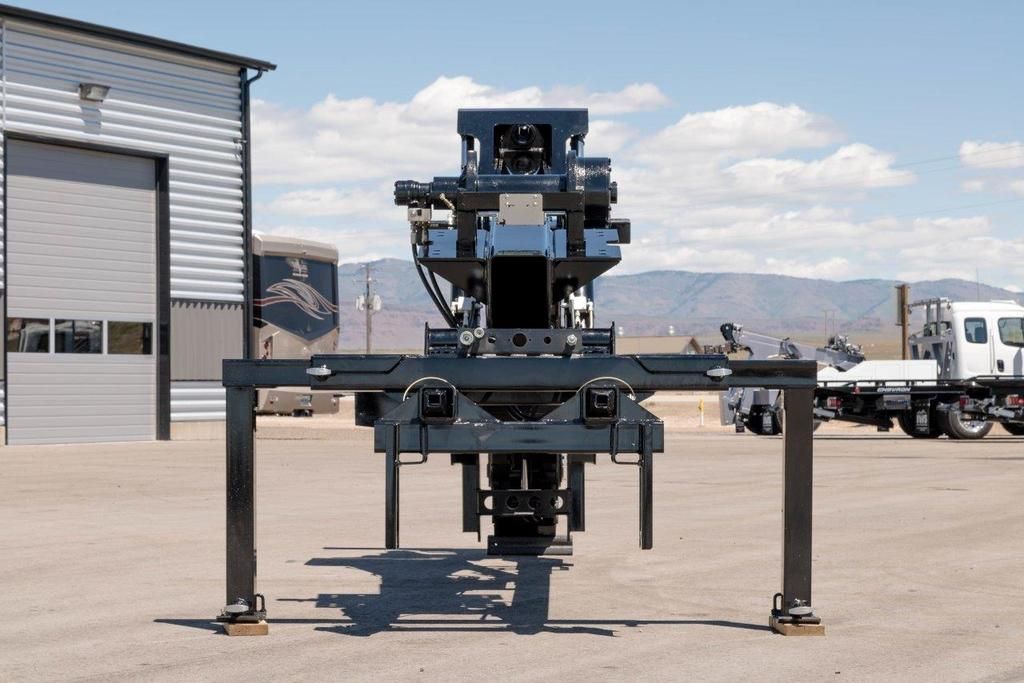
The unit comes standard with a 20, lb planetary winch, ’ of 9/16” wire rope and front legs that allow the unit to be easily removed in a matter of minutes so your truck can be multi-functional for both towing and pulling trailers. The DTU is designed to secure to your truck using a front lock-down bracket and your Fifth Wheel Plate. al: Spring offset to port “B” single solenoid B: Spring centered-single solenoid Bl: Spring centered-single solenoid C: Spring centered-double solenoid F: Spring offset-shift to center-single solenoid N: Without spring with detent D G 03–2C–VAC–72–DN P T 6 A B P T A B 22 0 P T A B 87 11 A P A B P T B P T B A T 2 P A 1 P A T B 3 T B P.OWNER’S MANUAL DTU GEN2 PARTS – PDFHolmes DTU | Miller Industries
