With the metering jets screwed into jet holders, the holders are in turn screwed into the solenoid outlets. rating calculated for a fuel-injected engine?. data” in this manual and in the valve manual for the respective pneumatically actuated the solenoid valves in Type / and the pneumatic actuator.
Troubleshooting Guide. Solenoid Troubleshooting Guide. Internally & Externally Switched Solenoids.
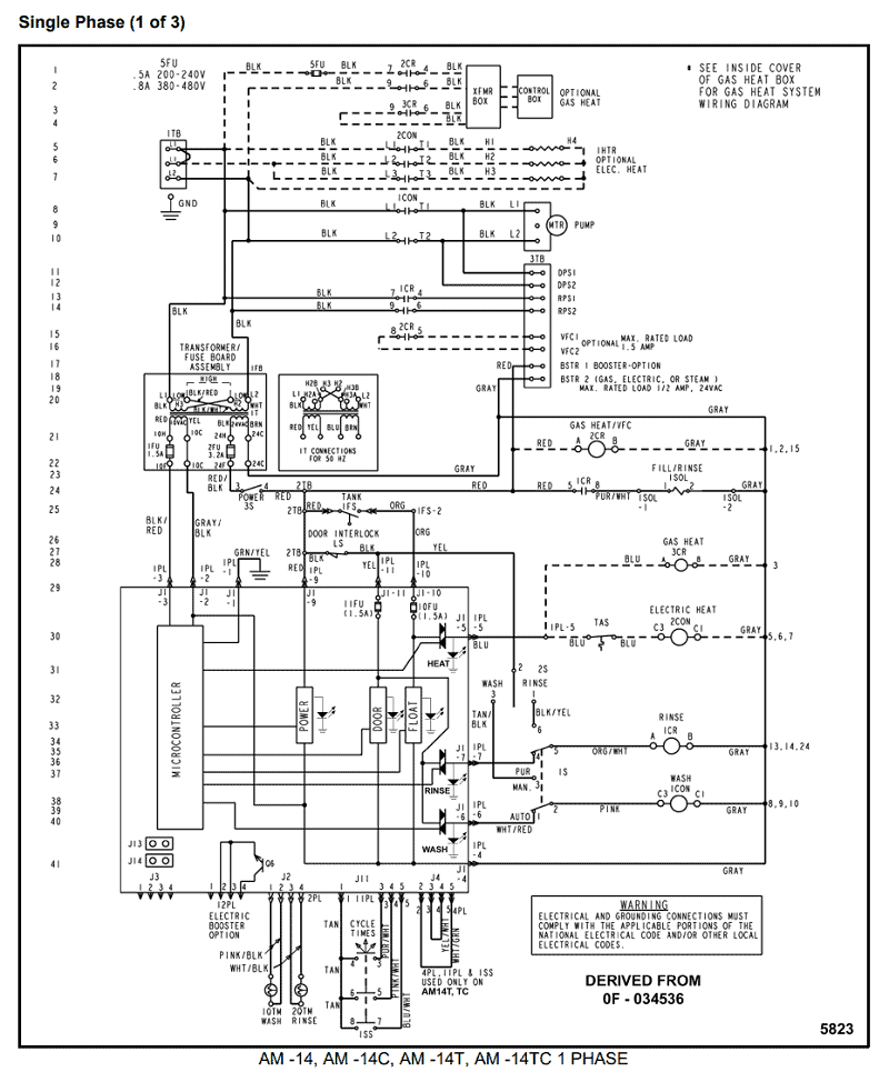
Push & Pull Type Solenoids. Manual essick humidifier wiring diagram old motor part# 1B, Has 4 wires coming from motor.
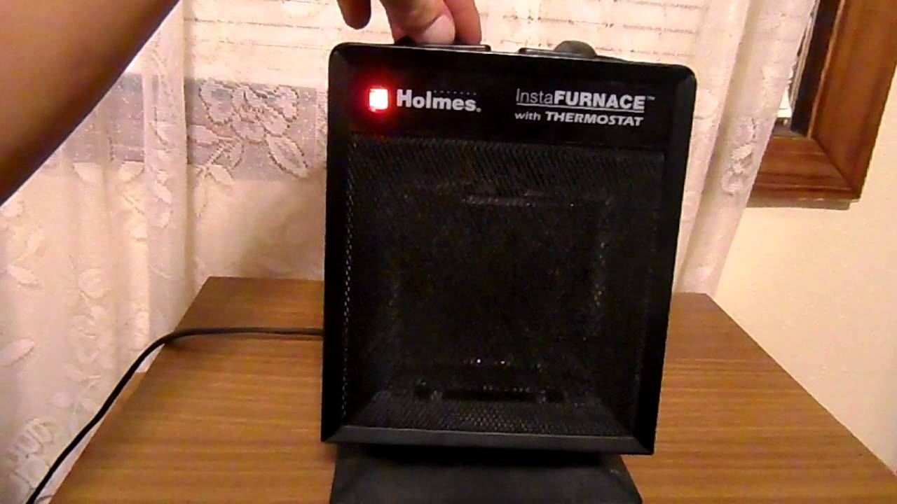
BLK-com,BRN-high, – Holmes Products. Product Manual (Revision A, 05/).
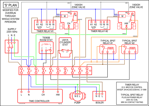
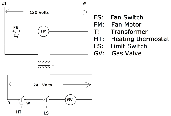
Original Instructions. Internally Switched Dual Coil Solenoids. Externally Switched Dual Coil Solenoids including .Most humidifier solenoid valves are operated on 24 Volt AC power, which is the predominant low voltage wiring standard for conventional HVAC controls.
24 Volt wiring is thin, 18 gauge wire – much smaller than or Volt line voltage wiring. Run a section of gauge wire from the “B” terminal on the solenoid to the “S” terminal on the starter motor.
Strip 1/4 inch of wire from the end of the wire using the wire strippers and then crimp a blue ring terminal on each end. Then connect the wiring to the terminals using the open-end wrench set.
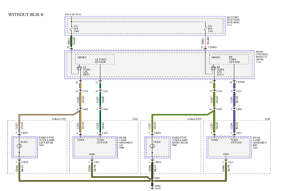
Sep 22, · Electric Power Supply Wiring for a Solenoid Power Supply and Wiring for a Solenoid Valve Question: I’m running water through a Ehcotech 12 VDC mA Electric Solenoid Valve. What amp 12 VDC power supply would I need to run this valve if the power supply is .
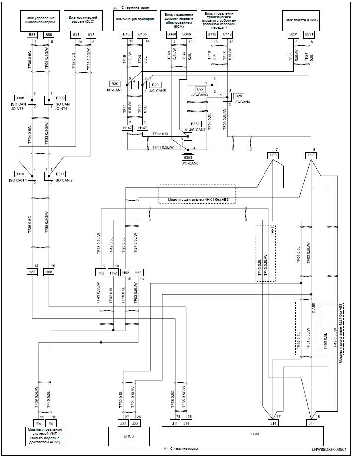
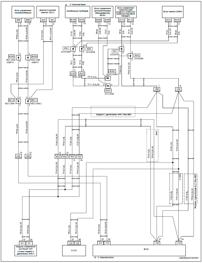
cac/bdp humidifier wiring diagrams models ending in , , evaporative humidifier wire identically as shown terminals for the manual humidifier control (mhc) c rw gy typical 24 vac terminal strip thermostat in furnace y g w rc remove wire “g” to “g” note: 18awg wire is acceptable for 24v installations. yellow.
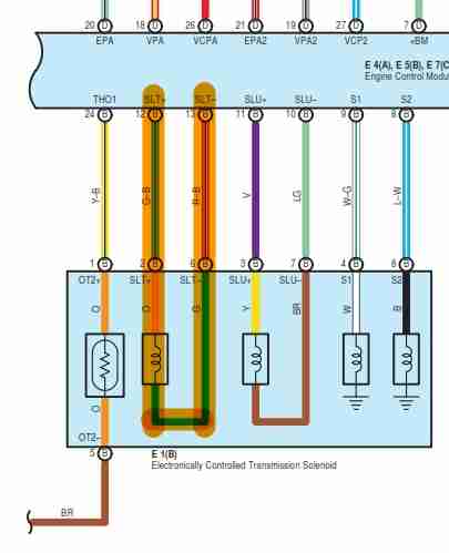
Valves with Integral Amplifiers Vickers valves with integral amplifiers are fitted with 7-pin connectors and all the connections to the valve are made through them. Figures 4 and 5 show the recommended electrical connection scheme for a KB type valve and the following information should be used when wiring the valves.
1) It is important to.How do you wire a Holmes tower fan motor it’s got six wires – FixyaSolenoid Wiring. Does it matter what wires go where? | PlowSite
