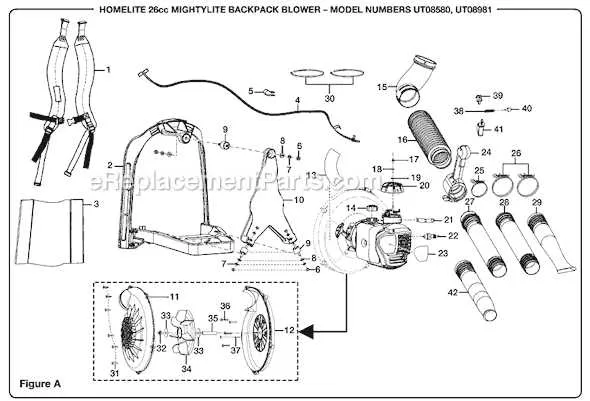
For efficient maintenance, the optimal position of the oil release fitting is located near the base of the engine casing, typically on the lower side to allow full drainage. Identifying this part is crucial to avoid spills and ensure a clean service operation.
Access point is generally marked by a threaded cap or screw, designed to be unscrewed with a standard wrench or socket. The component sits adjacent to the crankcase, often beneath protective covers or guards that require removal before servicing.
Precise positioning facilitates complete evacuation of fluids without tilting the equipment, minimizing the risk of contamination. Locating this fitting at the recommended spot enhances the efficiency of oil changes and prevents damage caused by residual fluid accumulation.
Attention to the exact fitting spot supports timely maintenance and prolongs the lifespan of the motorized device, ensuring operational reliability and performance.
Engine Oil Release Point Identification
The oil release bolt is situated at the lower rear section of the engine casing, near the base of the crankcase. It is easily accessible without removing additional components. Look for a hexagonal fastener approximately 1 inch in diameter, often positioned just behind the starter assembly.
Ensure the unit is placed on a flat surface and cooled down before attempting fluid evacuation. The sealing washer surrounding the bolt should be inspected and replaced if deformed or damaged to prevent leaks.
For efficient fluid removal, position a suitable container beneath this outlet to collect used oil. After draining, securely tighten the plug to the manufacturer’s specified torque, typically around 12-15 Nm, to avoid overtightening or stripping threads.
Reference marks or minor indentations on the crankcase casting can help quickly identify the exact spot for fluid extraction during maintenance checks.
Identifying the Exact Position of the Fluid Release Component on the UV80522 Model
The fluid release cap is situated at the lowest point of the lower engine casing, near the base of the crankcase. To access it, locate the small threaded plug positioned on the underside of the unit, typically close to the oil reservoir. This placement ensures complete evacuation of old lubricants during maintenance.
For precise identification, inspect the housing adjacent to the oil fill port; the release fitting is often marked by a hexagonal head designed for a wrench or socket tool. It is crucial to confirm that the component is not confused with other nearby plugs or sensors.
Removing this valve requires a compatible tool, usually a 3/8-inch or 10 mm socket, depending on the manufacturing specifications. Tightening torque values are generally specified in the service manual to prevent leaks or damage after refilling.
Ensure the unit is cool and positioned on a stable surface before attempting to unscrew the release fitting. Proper orientation and illumination aid in quick identification and avoid misplacement of sealing washers or O-rings commonly integrated within the assembly.
Step-by-Step Guide to Access and Remove the Fluid Release Component Safely
Locate the outlet valve beneath the lower housing of the equipment, near the base where the fluid collects. Ensure the unit is fully cooled down before proceeding to prevent burns or injury.
Prepare necessary tools: a suitable wrench or socket set matching the hex size of the valve fastener, and a container to catch expelled liquid.
Position the collection vessel directly under the valve to avoid spills. Slowly loosen the fastener by turning counterclockwise to begin draining.
Wear protective gloves and eyewear to shield from unexpected splashes or debris. Avoid sudden removal; allow fluid to drain steadily.
Once emptied, carefully remove the entire fitting by hand or tool, inspecting the sealing gasket for wear or damage.
Clean the valve seat and surrounding area with a lint-free cloth before reinstalling or replacing the component.
Reassemble by tightening the fitting to manufacturer torque specifications, ensuring a leak-proof seal.
Common Issues and Visual Checks Related to the Fluid Outlet Area
Regular inspection of the fluid exit point is crucial for maintaining proper operation and preventing leaks. Follow these steps to identify typical problems and ensure integrity:
- Seal Condition: Examine the rubber gasket or O-ring for cracks, brittleness, or deformation. Replace immediately if any damage is detected to avoid seepage.
- Thread Integrity: Check the threading on both the cap and the housing for wear, cross-threading, or stripping that could compromise tight sealing.
- Corrosion Signs: Look for rust or corrosion on metal parts surrounding the outlet. Corrosion can cause weakening and eventual failure of the closure mechanism.
- Contamination: Ensure no debris, dirt, or sludge buildup is present near the aperture, which could prevent proper sealing and cause fluid loss.
- Proper Tightness: Verify that the closure device is securely fastened without over-tightening, which might strip threads or damage sealing components.
For troubleshooting leaks or unusual fluid loss, visually compare the area with previous maintenance records or images, noting any new damage or wear patterns. Immediate replacement or servicing of faulty parts reduces the risk of more severe malfunctions.
- Clean the area thoroughly with a solvent or degreaser.
- Inspect all sealing surfaces under adequate lighting.
- Replace worn seals with manufacturer-recommended parts.
- Reinstall the closure element ensuring correct torque specifications.
- Perform a pressure or fluid retention test after reassembly.