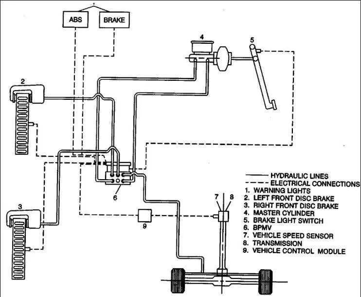
Ensure the correct alignment of the lever and its components before beginning the assembly process. Position the lever in its designated space, checking that all mounting points match the corresponding brackets on the vehicle’s frame.
Start by securing the hinge pin into place, ensuring it fits tightly and doesn’t allow any unnecessary movement. If necessary, use lubrication on the pin to ensure smooth motion once the assembly is complete.
Next, double-check the attachment of the return spring to prevent any slack. The spring should provide the proper tension, allowing the lever to return to its neutral position without delay. Improper spring tension could result in issues with lever responsiveness.
After securing the spring, confirm the placement of all fasteners and tighten them to the manufacturer’s specified torque settings. Tightening should be done in stages to avoid uneven stress on the components.
Finally, verify the operation of the assembly by moving the lever through its full range of motion. Ensure there is no resistance or sticking, and that the assembly performs smoothly under various pressures.
Installation Guide for Right-Hand Foot Lever
Start by locating the mounting points on the vehicle’s footwell structure. Secure the lever assembly using the pre-drilled holes designed for it. Ensure all bolts are tightened properly to prevent any movement during use.
Next, align the actuator rod with the appropriate bracket. Make sure that the connection is firm and there is no slack. Use a cotter pin or safety clip to secure the pin in place, ensuring the link cannot come undone during operation.
Verify that the lever swings freely without obstruction. It should move smoothly with no resistance. Adjust the mechanism if needed to achieve the correct range of motion.
Test the assembly by applying pressure on the lever. Confirm it engages the corresponding system fully and that there is no delay in response. Perform a final inspection to check for any loose connections or components.
Step-by-Step Guide to Identifying Pedal Components
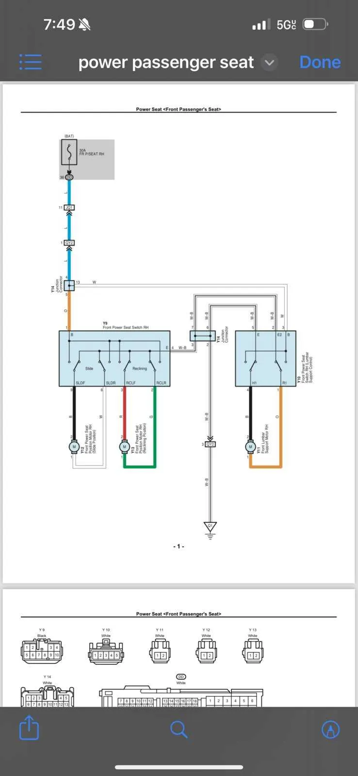
Begin by locating the mounting bracket, which secures the assembly to the vehicle’s frame. This bracket is typically fastened using multiple bolts, which should be removed first to free up the unit for inspection.
The actuator arm is the next key component to identify. It connects to the pivot mechanism and is responsible for transmitting the force applied by the foot. It usually includes a spring to ensure proper return movement.
Next, locate the linkage system, which connects the actuator arm to the primary mechanism. The system may involve a rod or cable, which requires inspection for wear or damage that could hinder performance.
Focus on the mounting points and their alignment. Misalignment can result in improper functioning. Ensure the parts are not worn or excessively lubricated, as this can affect their responsiveness.
Finally, examine the contact plate or pad, which interfaces with the vehicle’s system to initiate the desired function. It is important that this piece is not damaged and that it makes proper contact without slipping.
How to Properly Align and Mount the Pedal Mechanism
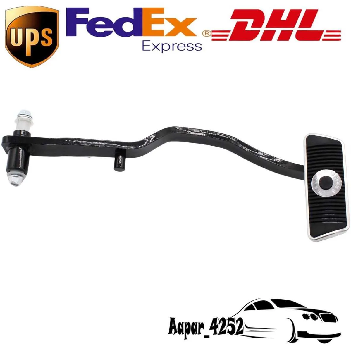
Ensure the component is positioned in line with the mounting brackets before securing it. Misalignment can result in improper function, leading to safety concerns.
- Start by verifying the location of the mounting holes on the support frame.
- Use a level to check the angle of the assembly to ensure it aligns with the rest of the components.
- Insert the main bolt into the designated mounting hole, making sure it fits without obstruction.
- Apply thread locker to the bolt to prevent loosening over time.
- Secure the nut on the bolt firmly, but avoid over-tightening to prevent damaging the frame.
Next, check the clearance around the mechanism to ensure smooth movement. If any resistance is felt, readjust the alignment.
- Double-check the distances from the pedal to surrounding parts to allow full range of motion.
- Verify that the mechanism does not rub against other components during operation.
- Test the operation by pressing the pedal to check for proper engagement and disengagement.
Once everything is aligned and functioning, inspect the system periodically to ensure continued reliability.
Common Mistakes and Troubleshooting During Setup
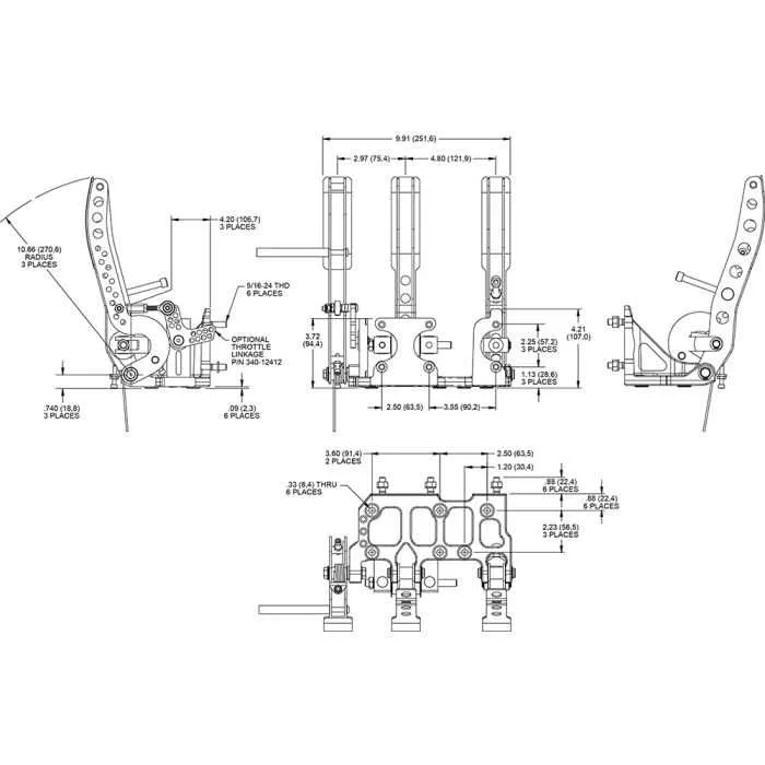
Ensure the correct alignment of the foot lever before securing it. Misalignment can lead to improper operation, causing the component to feel loose or unresponsive. Verify the mounting bolts are tightened to the manufacturer’s specifications to avoid any slack in the assembly.
Check for clearance between the assembly and surrounding parts. Insufficient space can cause friction or interference, hindering smooth function. It’s crucial to test the mechanism before completing the tightening process to confirm full movement without obstruction.
Inspect the linkage and connecting rods for any wear or damage. Even minor issues in these parts can lead to failure during use. Replace any worn-out components promptly to ensure safety and performance.
Double-check that the return spring is properly seated. An improperly positioned spring can cause inconsistent operation, especially when releasing pressure. If the spring feels weak or doesn’t return fully, it may need replacement.
Avoid over-tightening fasteners. Excessive torque can lead to distortion of parts, making the mechanism harder to engage or disengage. Always use the correct tool and torque settings as recommended by the manufacturer.
After completing the setup, test for proper feedback when applying pressure. If the response feels spongy or delayed, inspect the entire system for air pockets or fluid issues. Ensure that the hydraulic or pneumatic system is free of leaks.
Be mindful of securing all fasteners in their proper sequence. Failure to follow the correct order can lead to uneven force distribution, which may result in operational issues down the line.