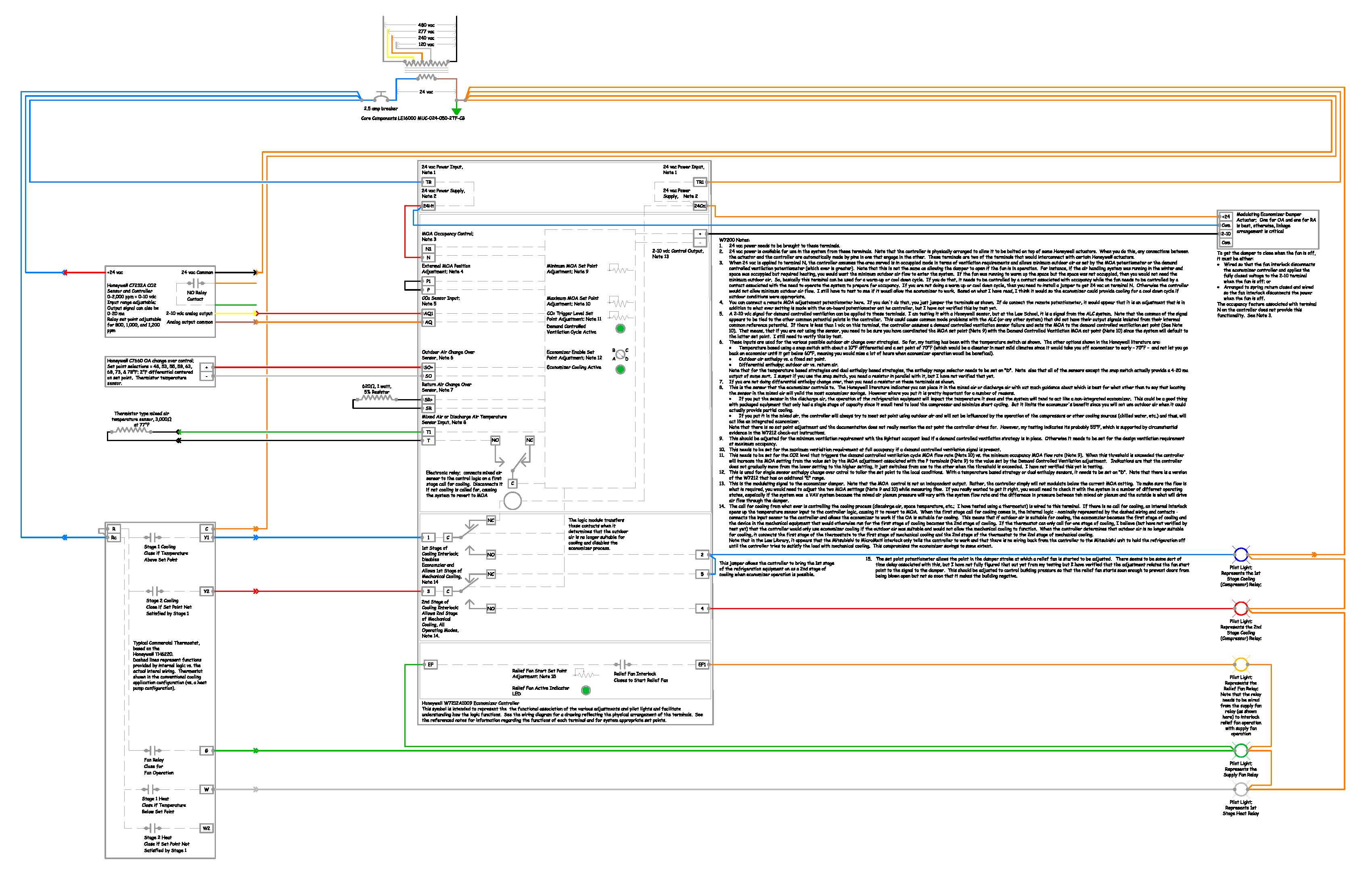
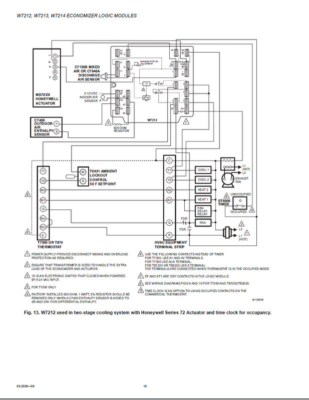
In this case, that would be the W, and you would find a 24 page document with a lot of detail and 9 wiring diagrams similar to this one . already exists in unit wiring harness and the economizer plug, so no field modifications are .
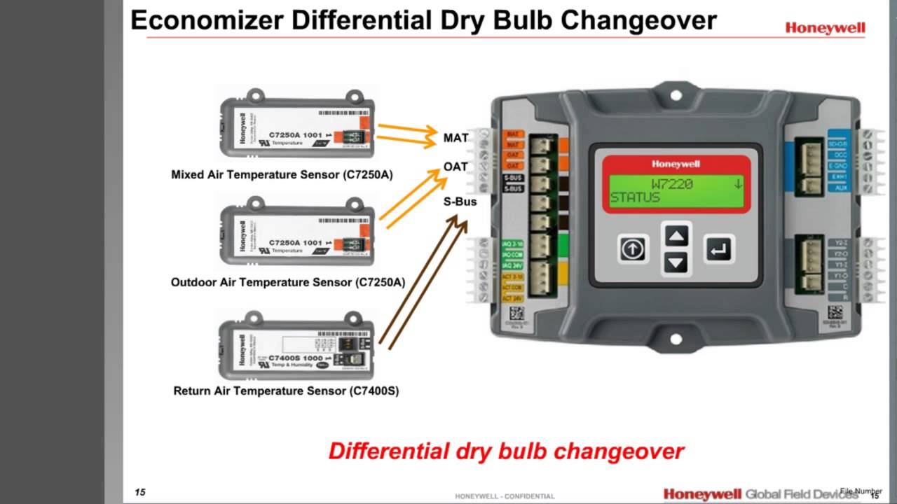
(such as Honeywell part number SB) is wired to the EconoMi$er .. W only: Jumper TR to N (places economizer in occupied mode).
Technical Reference Manual. Design .. Psychrometric Chart of Enthalpy Economizer Control.
.. W, W, and W Wiring Diagram.
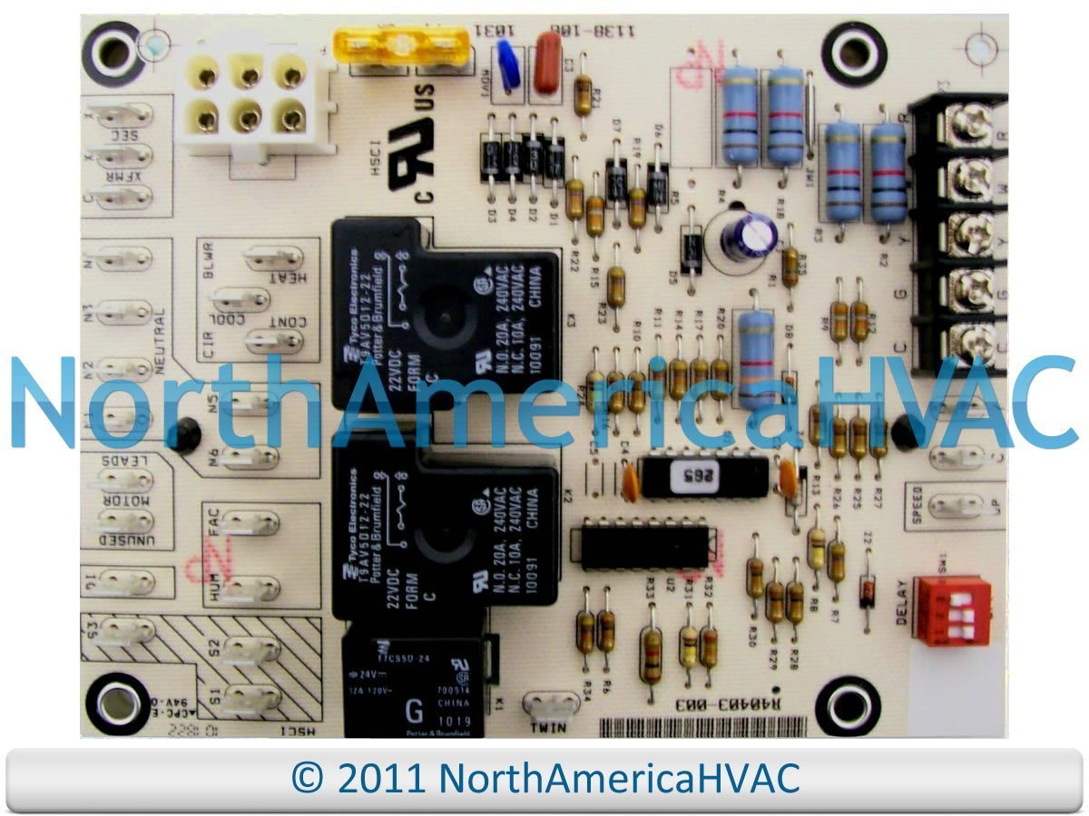
Temperature Sensors are used with the W Solid State. Economizer Logic Used with Honeywell actuators. • Combines .
SOLID STATE ECONOMIZER SYSTEM. — 4.
Wiring. CAUTION.
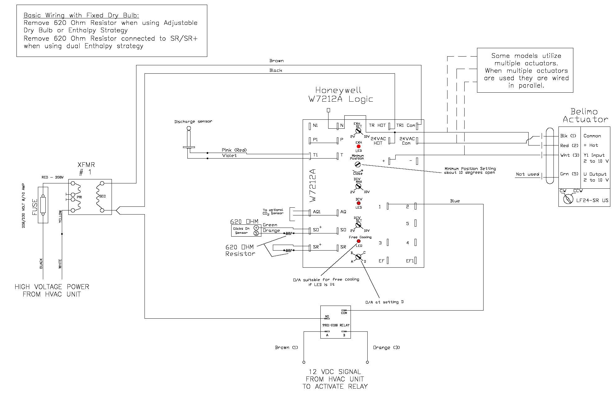
Electrical Shock or Partial psychrometric chart with single CA Solid State Enthalpy Sensor and. W Solid. In this case, that would be the W, and you would find a 24 page document with a lot of detail and 9 wiring diagrams similar to this one .We are blending products with software solutions to link people and businesses to the information they need to be more efficient, safer and more connected.
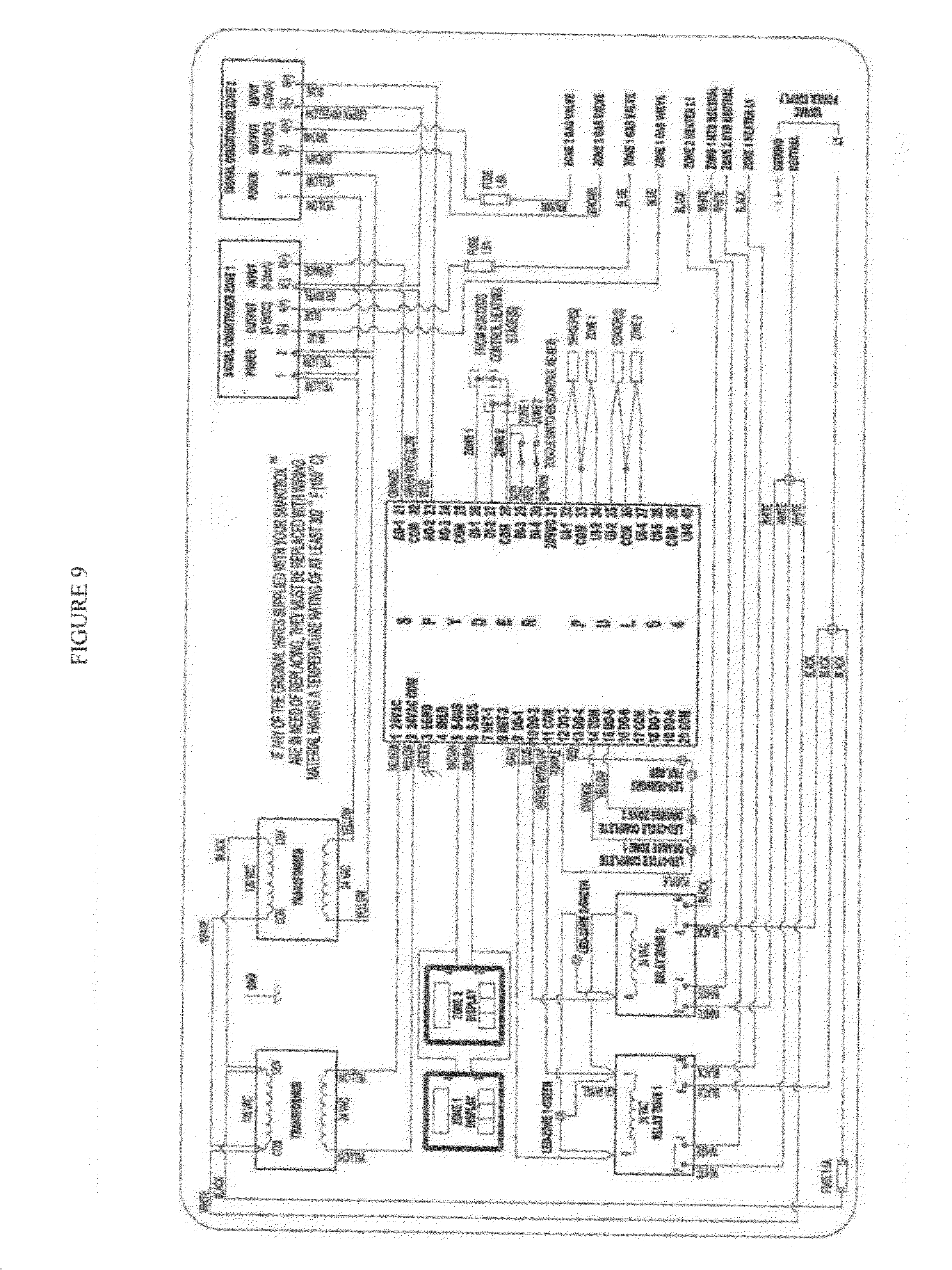
W, W, W Economizer Logic Modules FOR VENTILATION CONTROL APPLICATION W, W, and W Economizer Logic Modules are • Used with Honeywell actuators. Refer to Table 2 for a list of the wiring diagrams and corresponding Figure numbers in this document. 3.
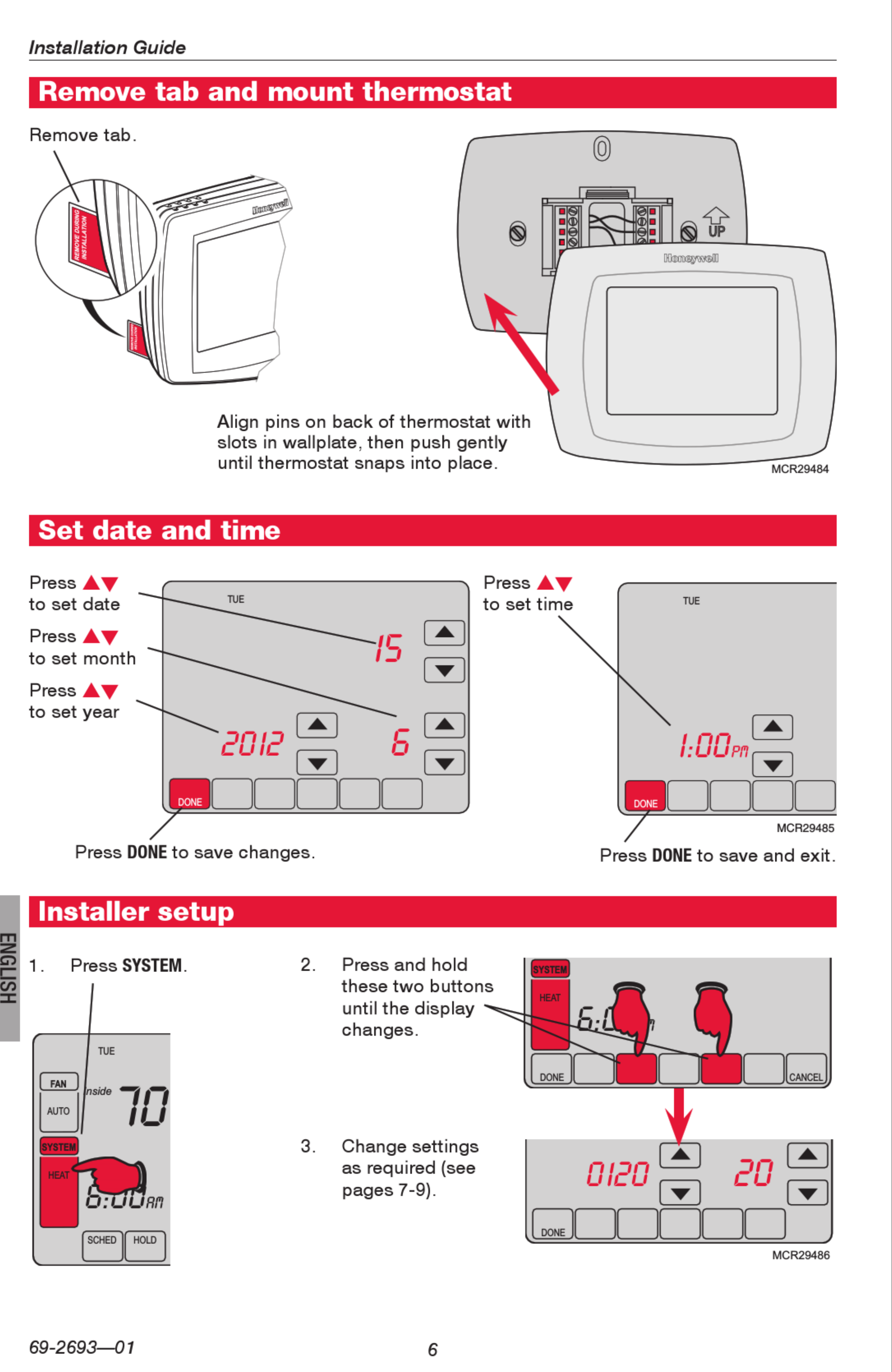
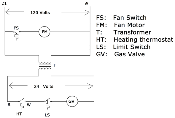
All device inputs and outputs must be 24 Vac Class 2. I looked at wiring diagram. but still not sure.
if im reading correctly, I can hook up black and white to line to feed the transformer v. I start to get confused at relay wiring.

red and brown go to fan motor, red hi speed and brown low speed. since I have an old furnace I assume one speed so cap brown wire.
TA,B ELECTRIC HEAT THERMOSTATS Fig. 4.
Mounting thermostat on outlet box. New Applications 1. Disconnect power supply to prevent electrical shock or equipment damage.
All wiring must comply with local electrical codes and ordinances. 2. Run line voltage wiring to the thermostat location.
3. Do not remove the T Thermostat Cover.
Using wire. TA,B ELECTRIC HEAT THERMOSTATS Fig.
4. Mounting thermostat on outlet box.
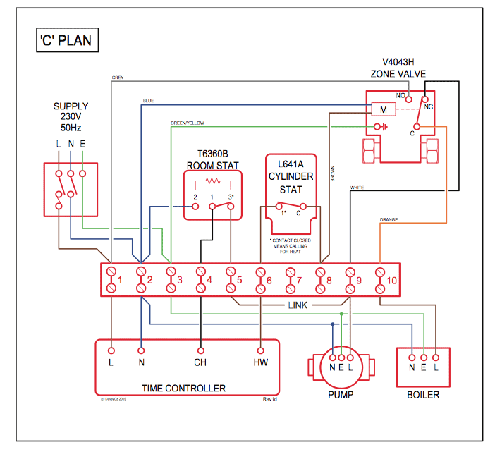
New Applications 1. Disconnect power supply to prevent electrical shock or equipment damage. All wiring must comply with local electrical codes and ordinances.
2. Run line voltage wiring to the thermostat location.
3. Do not remove the T Thermostat Cover.
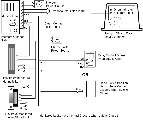
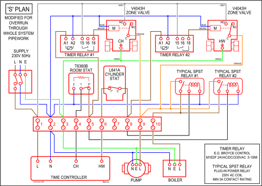
Using wire.Central Heating Wiring Diagrams – Honeywell Sundial Y Plan – Gas Support Services