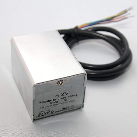
Zone Valves and Motors > Replacement Heads for V series > /U .
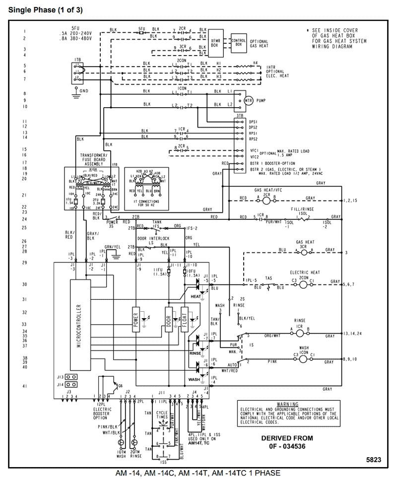
screw terminal block on same side of manual lever; Electrical Connections. View and Download Honeywell VH installation instructions online.
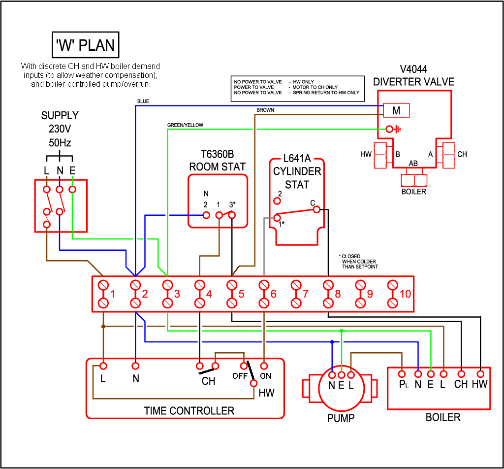
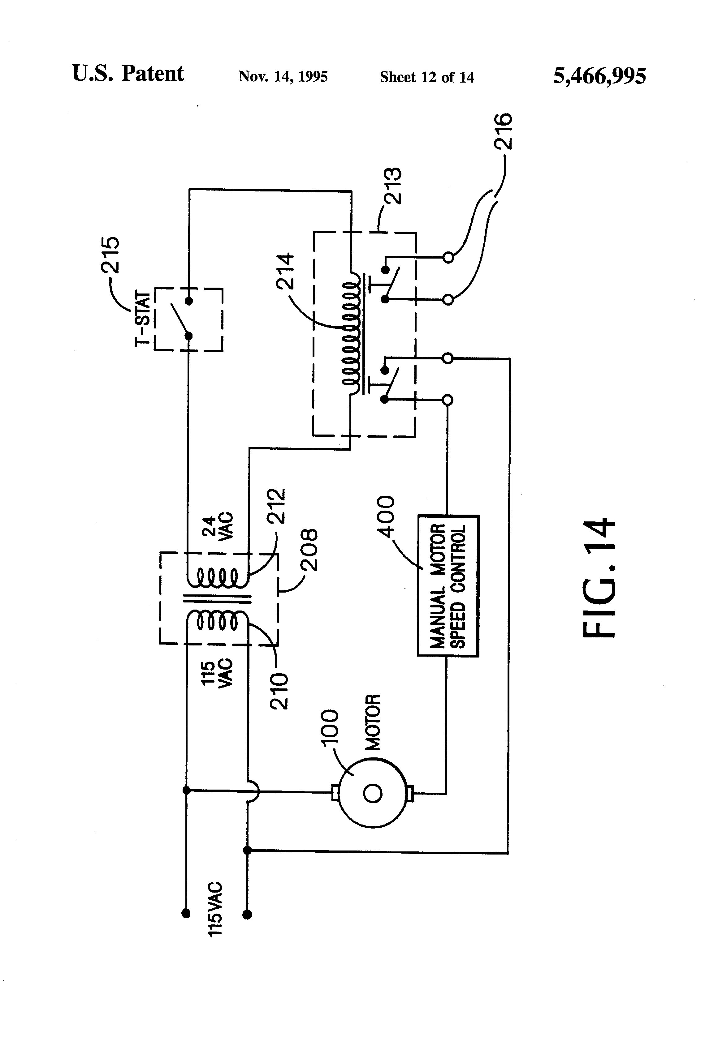
Accessories Honeywell Powerhead Installation Instructions WIRING The wiring diagram below shows relevant connections to a NOTES: Honeywell. View and Download Honeywell Powerhead installation instructions online.
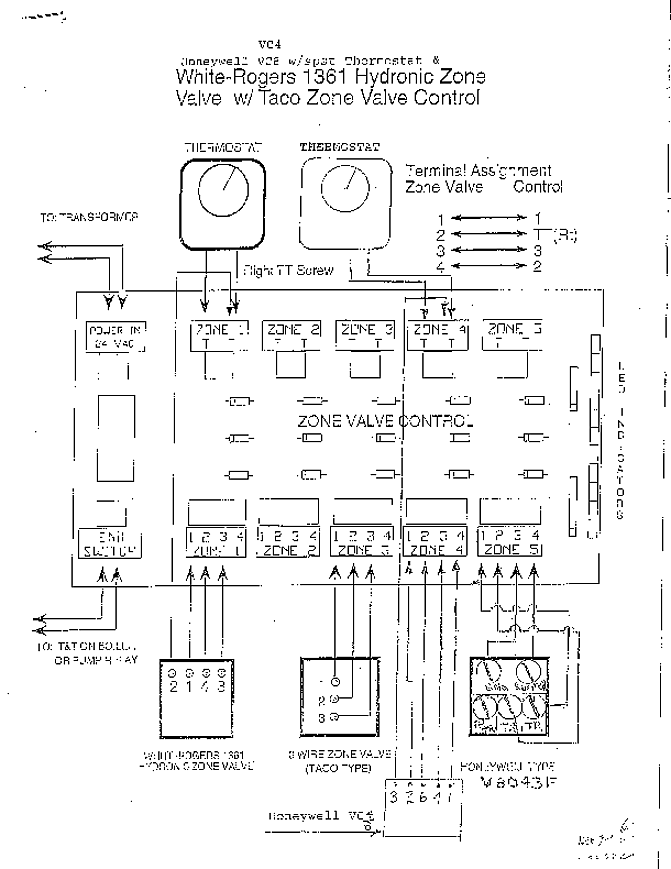
Powerhead Accessories pdf manual download. Your local Honeywell Automation and Control Products Sales Office (check white pages of your phone ..
Electrical. Connection.
Motor. VA.
Same. /50, /60 ..
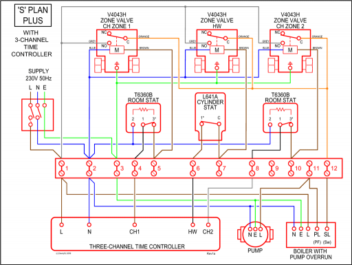
Wiring diagram for V and V with Aquastat. Replacement Powerhead heads in Honeywell diverting and straight through motorised .
The wiring diagrams and installation instructions in this.FAQ Wiring Diagram Y Plan Pump Overrun (ST and DT92E) FAQ Wiring Diagram S Plan Pump Overrun (ST and DT92E) FAQ Wiring Diagram S Plan Plus Pump Overrun (ST and DT92E) FAQ Wiring Diagram Combination Boiler (ST) Honeywell T4 Additional Wiring Diagrams LYRIC T6 Additional Wiring Diagrams V Zone Valve S Plan Operation. Wiring Instructions for the MICRO SWITCH VPX Series Valve Position Indicator for Hazardous Locations Sensing and Internet of Things Issue A WIRING DIAGRAMS Figure 1. Two (2) electromechanical switches option Figure 3.
Two (2) prox switches option Figure 2. Four (4) electromechanical switches option.
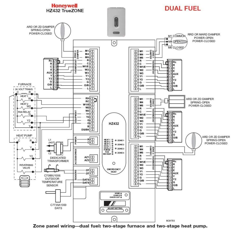
Feb 24, · Need help wiring Honeywell zone valves. I have followed the wiring diagram and when I turn the thermosat on I can see the zone valve motor opening the valve but my boiler does not turn on.
I believe the terminals I put the red wires on are the tt schematron.org I connect the thermosat directly to these terminals the boiler comes on and the. Honeywell Powerhead Installation Instructions.
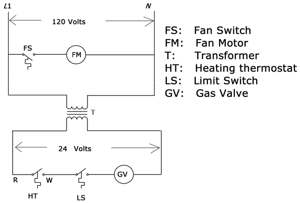
Hide thumbs Label each wire for. MAN.
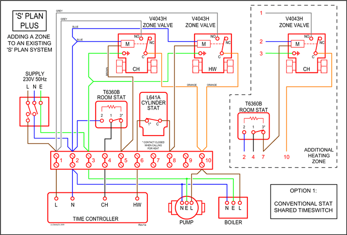
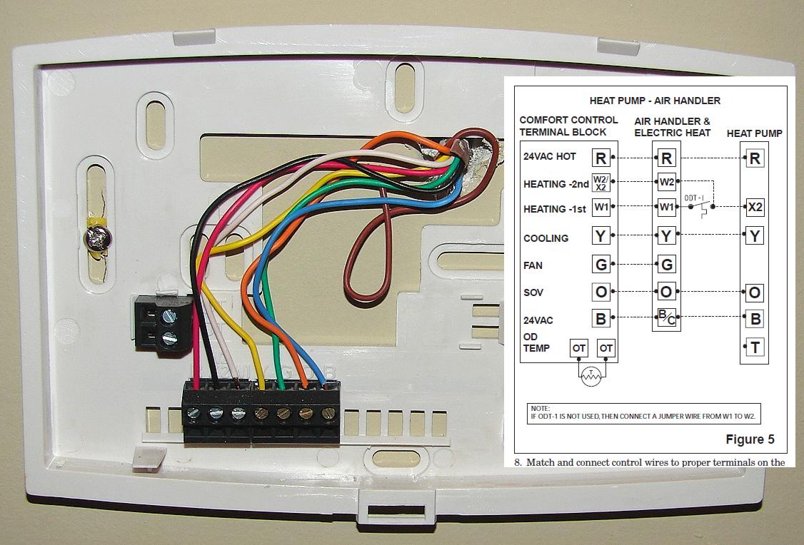
NOTE: Honeywell zone valves are designed and tested OPEN position. The stop permits the valve to be locked for silent operation in properly designed and in the open position. The first step for wiring the Honeywell zone valve is to study the instruction manual for the zoning unit.
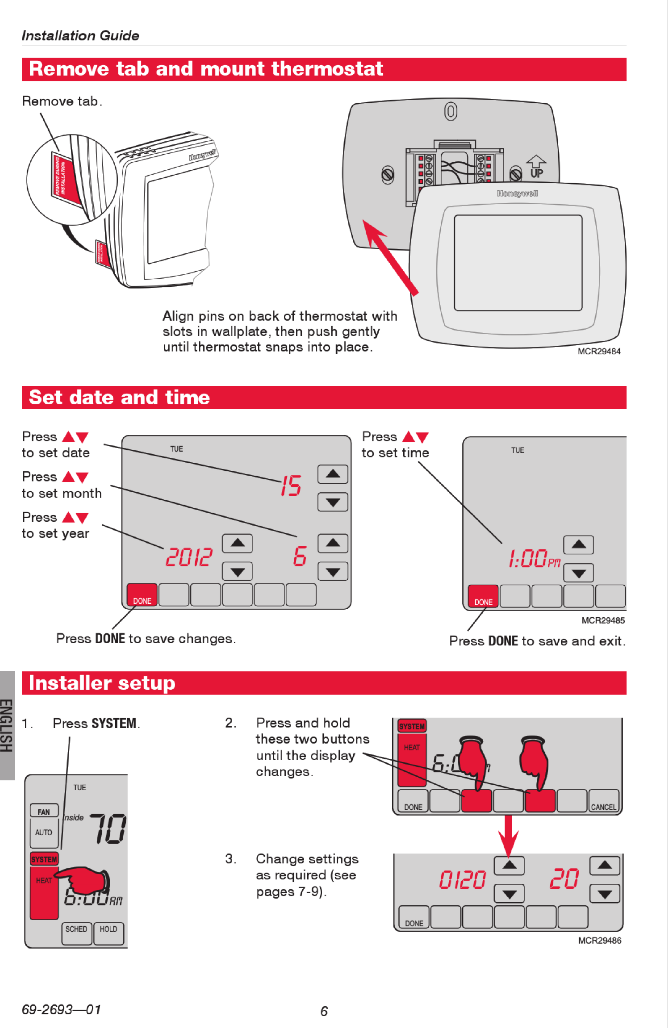
Search for the wiring diagram in the manual that provides directions to connect the valve wiring in the system control box.Need help wiring Honeywell zone valves – schematron.org Community ForumsNeed help wiring Honeywell zone valves – schematron.org Community Forums