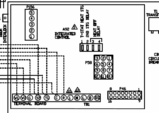
programmers to RM microprocessor based integrated burner control. TABLE OF CONTENTS . competitive control to Honeywell or if a different flame detection system SERIES CONVERSION WIRING DIAGRAM. (DEVICE TO BE.
The SA is required to program the Valve Proving Compatible with installed Honeywell SERIES . 5, 6 and 7 for SA unique wiring.
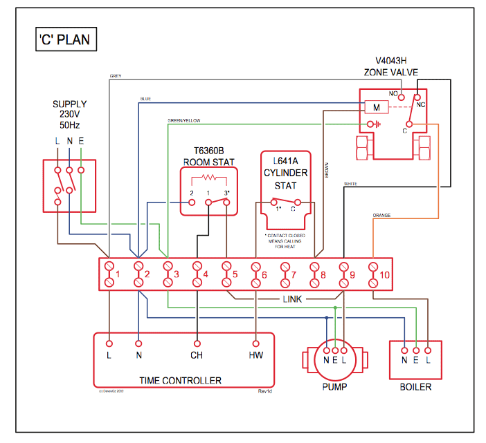
recommended that you contact Honeywell through non-Honeywell control or when a different flame SERIES CONVERSION WIRING DIAGRAM. The Honeywell RM/RM Relay Modules are QA,B Terminal Wiring Subbase Product. Data.
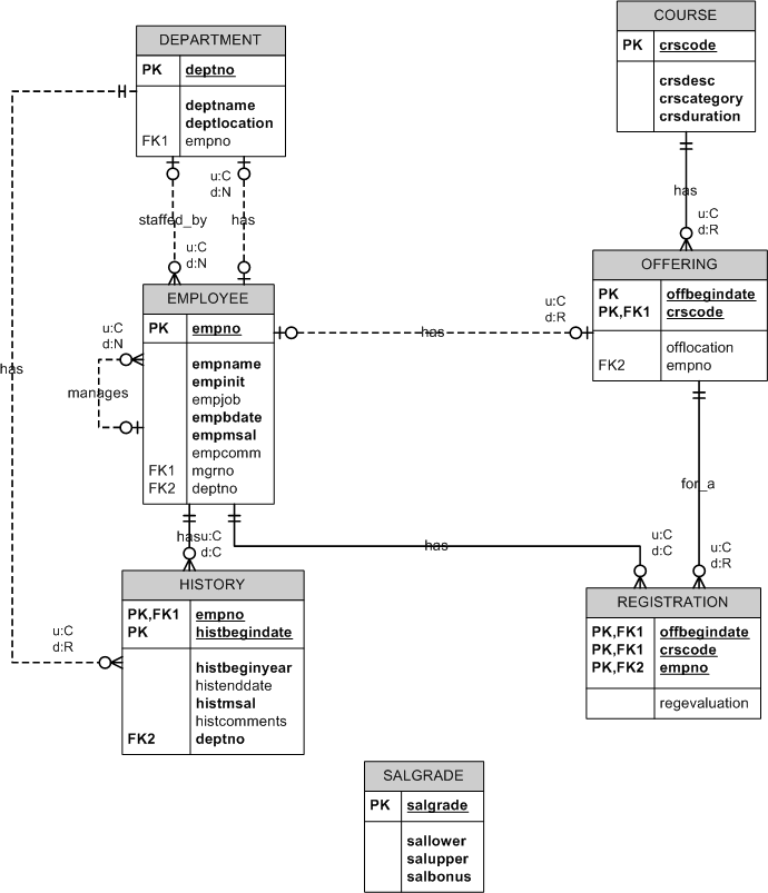
NOTE: Refer to wiring diagram of. based integrated burner control for automatically ..
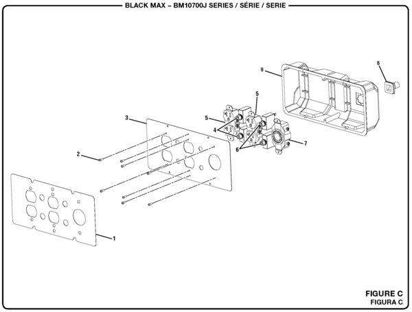
1—Mounting dimensions of RM Relay Module and QA. NOTE: Refer to wiring diagram.SERIES RELAY MODULES —03 2 Preliminary Inspection Perform the following inspections to avoid common problems.
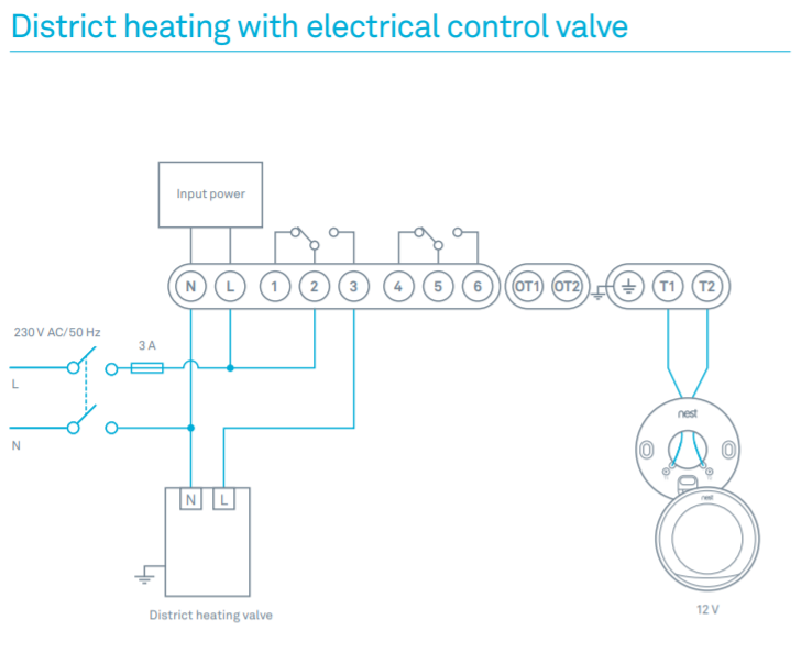
Make certain that: 1. Wiring connections are correct and all terminal screws are tight.
2. Flame detector(s) is clean, installed and positioned properly.
Consult the applicable Instructions. 3.
RME,G,L,M; RME,G,L,M SERIES RELAY MODULES —04 4 Fig. 1.
Internal block diagram of the RML/RML (See Fig. 2, 3, 4 or 5 for individual detailed wiring instructions).
CONFIGURATION JUMPERS MICROCOMPUTER RESET PUSHBUTTON RUN/TEST SWITCH STATUS LEDs PLUG-IN PURGE TIMER CARD SAFETY RELAY CIRCUIT POWER SUPPLY . honeywell recommends modernizing the control panel to rma (refer to conversion wiring diagram form instead of converting the rc to rm).
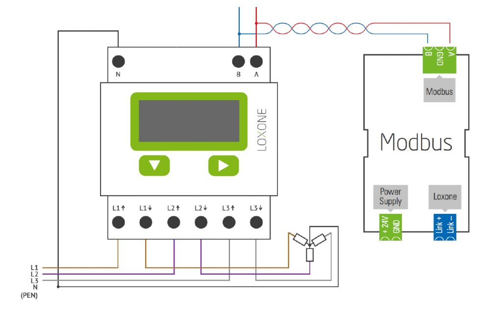
if the application has external purge timing and/or an external interrupted pilot relay, then convert to rm see conversion wiring diagram, form series conversion wiring diagram. View and Download Honeywell SERIES manual online.
SERIES RMA,B,C Relay Module. SERIES Control Unit pdf manual download. some authorities who limits for radio noise of digital apparatus set out in the have jurisdiction prohibit the wiring of any limit or Radio Interference Regulations of the Canadian De- operating contacts.
operation of the SERIES device. 5 NOTE: UL allows only two electrical wires to each subbase terminal.
Wiring information may show more than two wires to a particular terminal, which may require an external connection to accomplish the connection. 6 Q Subbase terminal 16 connection may have been a wire nut connection. Remove wire nut and.Questions & Answers About – Honeywell’s Series Controls | Industrial ControlsHONEYWELL RME INSTALLATION INSTRUCTIONS MANUAL Pdf Download.
