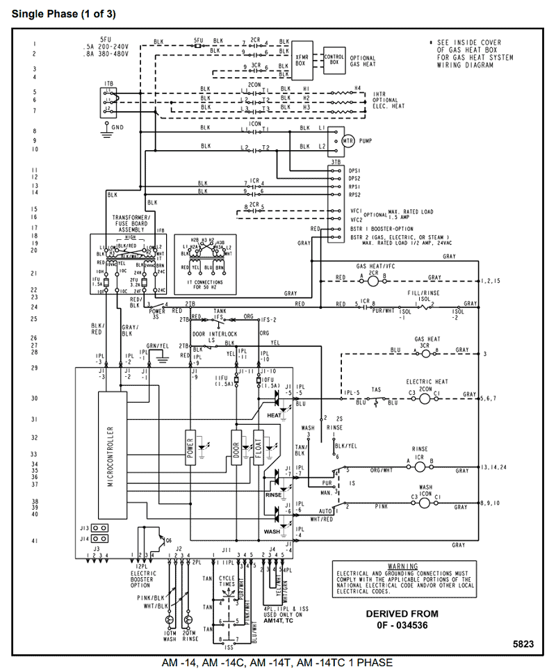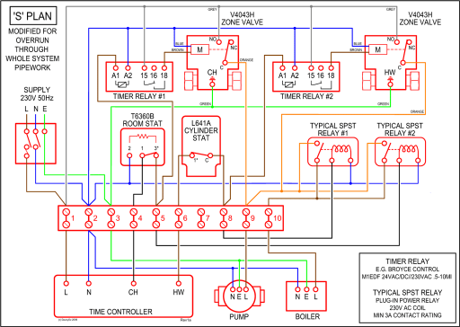
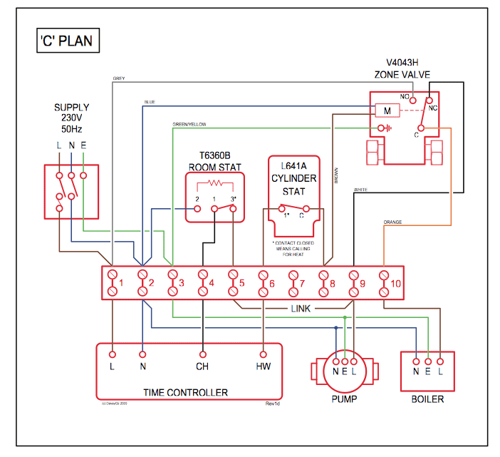
Thermostat Wiring for Dummies
Honeywell thermostat wiring instructions for 4 & 5 wire applications. Learn how to wire basic thermostats and digital thermostats to operate heat and cooling.
TBC5x14(x). 1 or 2 floating 1 or 2 analog outputs. Y 2.
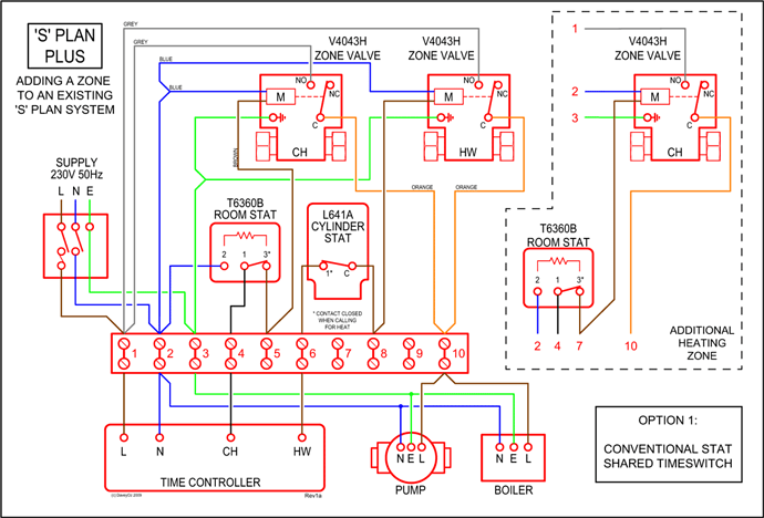
Y 1. G Heat Pump Scom.
BI #2. UI 3 COS/COC/SS. Terminal Description.
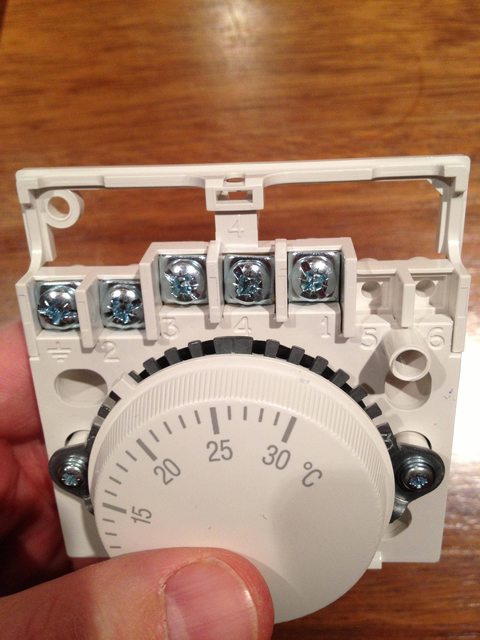
X. Fan-H. The Honeywell CT87N is one of the models in the trademark analog-dial Honeywell Do not use the C or X wire at all.
Set the fan switch in the center of the thermostat base to “E” if you have a heat pump or electrical heating system. TBF Heating with reheat: Analog duct heater and electric TB Series RTU and Heatpump Thermostat Selection. .
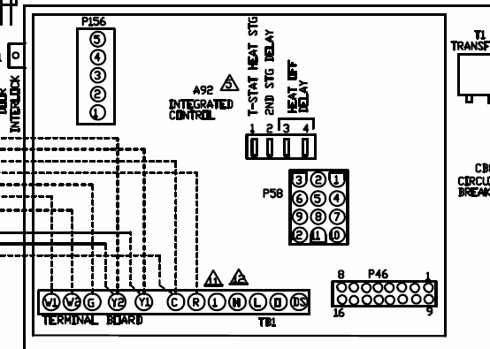
Appendix C: Thermostats occupancy sequence of operation schematic. . For full explanation of parameters refer to the TB Series Installation Visit schematron.orgell.
com for. Also see Honeywell Thermostat Wiring Diagrams – Honeywell Wall TF type Thermostats Place a jumper (piece of wire) between Y and W if you have a heat pump Honeywell traditional T87 Round wall thermostat, analog (C) Daniel . C / X / B – do not connect – tape off bare wire ends; Y2 wire to Y2 terminal on the.Thermostat Wiring and Wire Color Chart – Thermostat Wiring Colors Code; Tstat Terminal Designation: Color of Wire and Termination: R – The R terminal is the power. This comes from the transformer usually located in the air handler for split systems but you may find the transformer in the condensing unit.
How to Wire a Thermostat | HVAC Control
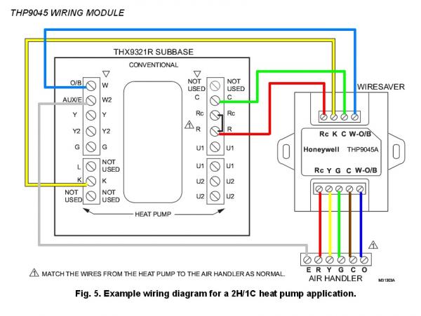
The “O” and “B” terminals on a Honeywell digital thermostat send power to a heat pump’s reversing valve. The “O” terminal operates the reversing valve during the cooling cycle and the “B” terminal operates it during the heating cycle.

The heat pump’s wiring diagram identifies the . 5 Wire Honeywell Thermostat Wiring.
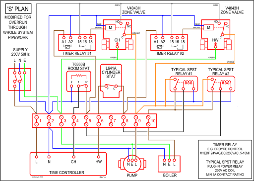
Some programmable thermostats (e.g. Honeywell Prestige wiring requirements) need a minimum of 5 wires, and maybe more depending on what features you want to operate (humidifier, etc).
Wiring Instructions for the MICRO SWITCH VPX Series Valve Position Indicator for Hazardous Locations Sensing and Internet of Things Issue A WIRING DIAGRAMS Figure 1. Two (2) electromechanical switches option Figure 3.
Two (2) prox switches option Figure 2. Four (4) electromechanical switches option While Honeywell may provide. Heat Pump Thermostat Wiring Chart. This is for use for heatpumps. You should % make sure that you have a heat pump system and not an air conditioner with electric heating strips as it is a common mistake for people to misidentify their HVAC systems.Thermostat Wiring for Dummies – How Anyone Can Do ItHeat Pump Thermostat Wiring Chart Diagram – HVAC Heating Cooling
