L/L Aquastat Controllers are intended for use in residential-type .
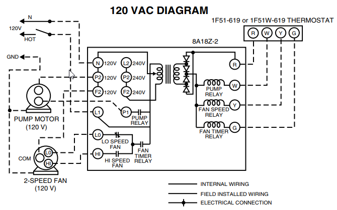
Follow the appropriate wiring diagrams shown on the inside of the front cover of the. Honeywell Aquastat LA Manual Online: Wiring Diagrams.
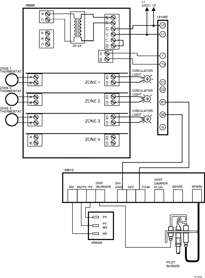
T87F R RELAL1 PUMP 1 (HOT) L2 LA 2 G L2 LC C1 C2 B2 B1 1 POWER SUPPLY. Boiler Aquastat Relay Troubleshooting and Control Wiring!
Boiler Aquastat, How it Works, Troubleshooting, and Control Wiring. .
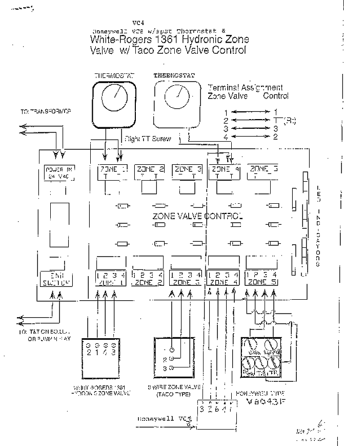
4 Wire, 5 Wire Honeywell Zone Valve Wiring, Troubleshooting, Dismantling – Duration: honey well triple action aquastat wiring explained,, low limit, reverse action, with additional zone relays how to properly schematron.org prevent loosing. Aquastat® Relays. APPLICATION use with Honeywell Smart Valve SV/ SV .
WIRING. IMPORTANT.
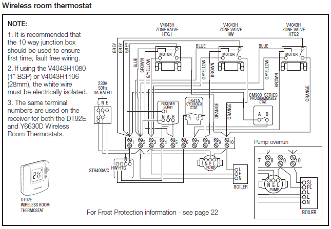
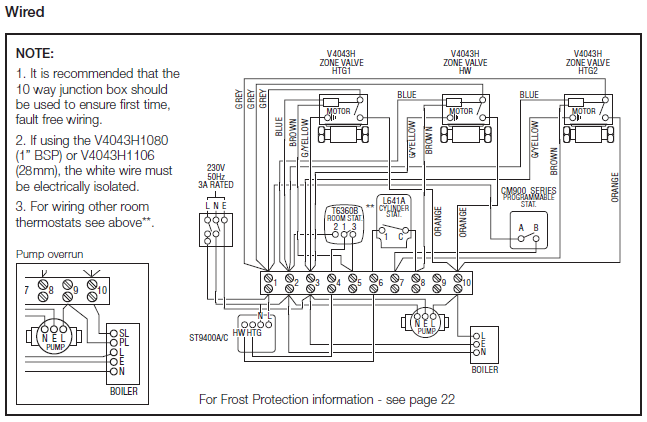
The terminals of these Aquastat® Relays are.FAQ Wiring Diagram Y Plan Pump Overrun (ST and DT92E) FAQ Wiring Diagram S Plan Pump Overrun (ST and DT92E) FAQ Wiring Diagram S Plan Plus Pump Overrun (ST and DT92E) FAQ Wiring Diagram Combination Boiler (ST) Honeywell T4 Additional Wiring Diagrams LYRIC T6 Additional Wiring Diagrams V Zone Valve S Plan Operation. page 5: wiring diagrams.
la,e,j aquastat® relays t87f t87f t87f r r r relay pump pump pump (hot) la orange white c black burner ignition rg power supply. provide disconnect means and overload protection as required. control case must be connected to earth ground.
use grounding screw provided. ma b1 is 1/4 in.
High or Low limit Aquastat Controller with F to F operating temperature, 5 F fixed differential, and 1/2 in well Sales/Promotional Materials Residential Combustion Application Selection and Cross-Reference Guide. Wiring-Typical connection diagram for an .
Wiring Diagram Honeywell Ra89a – Just Wiring Data Honeywell Ra Wiring Diagram Reinvent Your Wiring Diagram \u Honeywell Aquastat Relay Wiring Wiring Diagram Honeywell Ra89a. Honeywell Triple Aquastat Wiring Action – You can safely leave the current honeywell triple aquastat it in place. A mechanical triple aquastat is a very reliable.
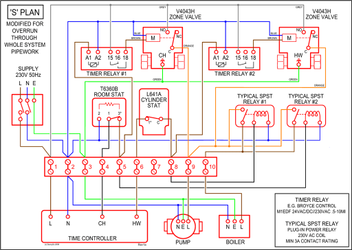
Wiring Disconnect power supply before connecting wiring to prevent electrical shock or equipment damage. Make sure all wiring complies with local electrical codes and ordinances. The case has a knockout for 1/2 in.
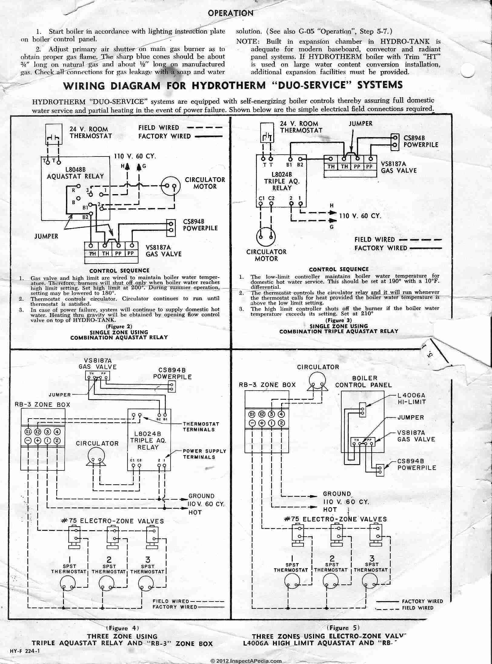
conduit. Fig.
3 and 4 show typical wiring diagrams of Aquastat¤ Controllers used in heating systems. Fig.
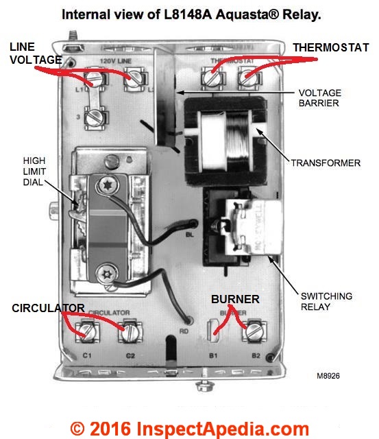
1. Internal view of.wiring honeywell aquastat to a L – schematron.org Community ForumsWiring Diagrams – Honeywell UK Heating Controls
