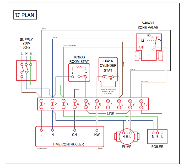
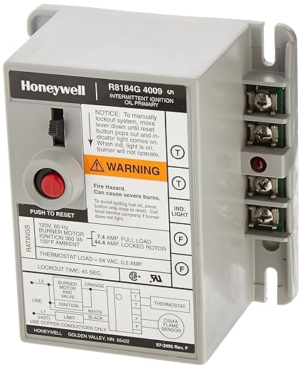
I have a Honeywell Rg Protectorelay Oil burner control and i have p > 3 schematron.org to powerorange to burner black and. honeywell RG wiring diagrams – Honeywell Protectorelay Oil Burner question.
Get Honeywell RG How to Guide. Get all Honeywell manuals!
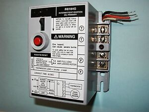
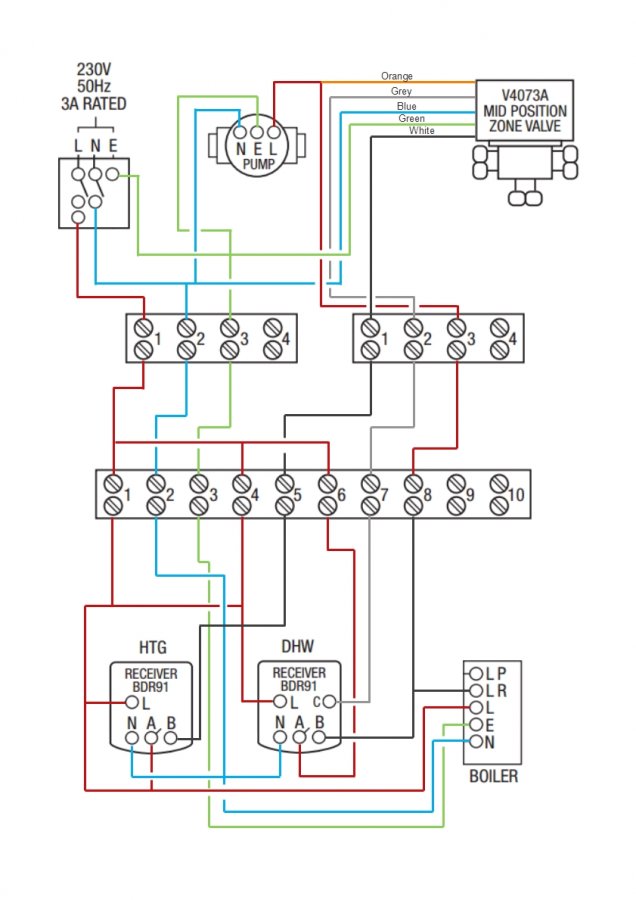
Leave enough slack in the wires to permit easy access into the junction box. DIAGRAM OF RM WITHOUT 4 X4 JUNCTION MOUNTING LOCKOUT INDICATOR.
1—Wiring diagram of RM. CHOOSE LOCATION.
• Mount the RM on a 4 x 4 inch junction box, directly on the burner housing, or inside the appliance. Features.
Controls oil burner, oil valve (if desired) and the ignition transformer in response to a call for heat. Solid state flame sensing circuit.
LED on terminal.Honeywell RG Protectorelay Oil Burner Control with 15 s Safety Timing, Alarm Outputs and Manual Safety Switch Honeywell RG International Oil Burner Control. out of 5 stars $ Honeywell RU Universal Electronic Oil 3/5(4).
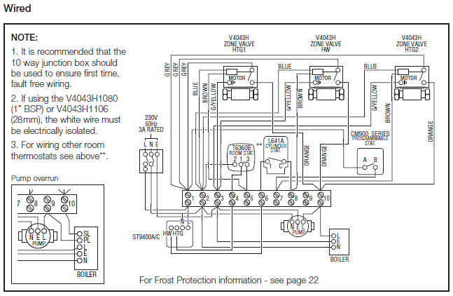
Wiring-Wiring for R Wiring-Wire and mount F (66 C) maximum ambient temperature oil primary control Installation Materials-Replacing RG with RU Wiring (English) Installation Materials-Câblages pour remplacer RG avec RU (French). I am looking for the wiring diagram for the junction box wiring under the protector relay.
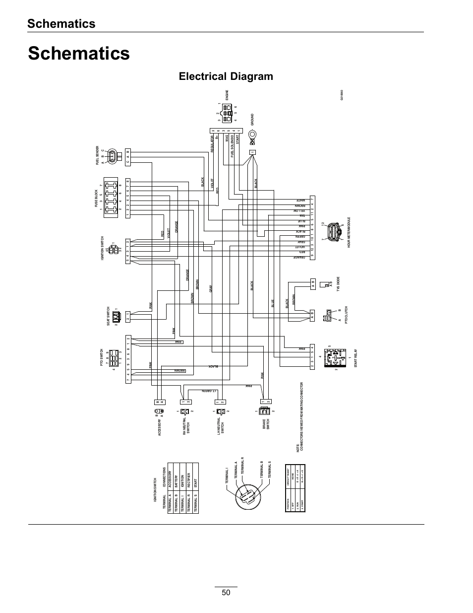
I removed a honeywell RG & installed a honeywell RG The new relay adds a Red LED indicator and a manual shut off switch. I am also looing for the correct .
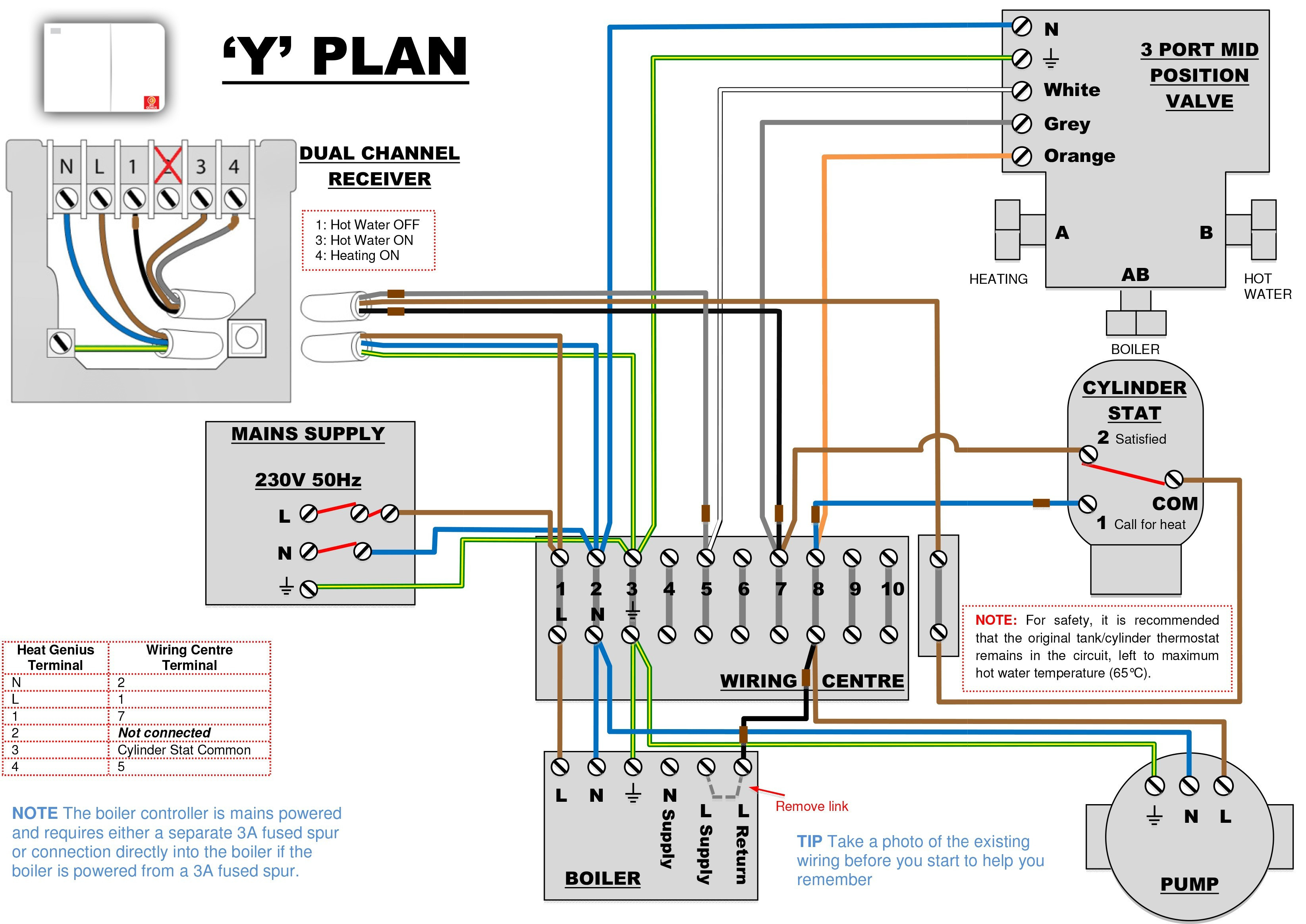
page 1: make wiring connections and mount control. power supply.
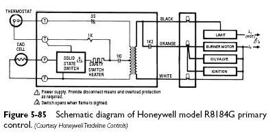
provide disconnect means and overload protection as required. to use r with line voltage controller, jumper t-t terminals and connect line voltage thermostat in series with limit controller.
3 —1 CHECK CAD CELL schematron.orgnect power at system switch, circuit breaker or fuse. schematron.org cell face with soft cloth.
schematron.org sure cell is seated securely in socket.Honeywell RG : How to GuideHoneywell RG wiring diagrams – Fixya