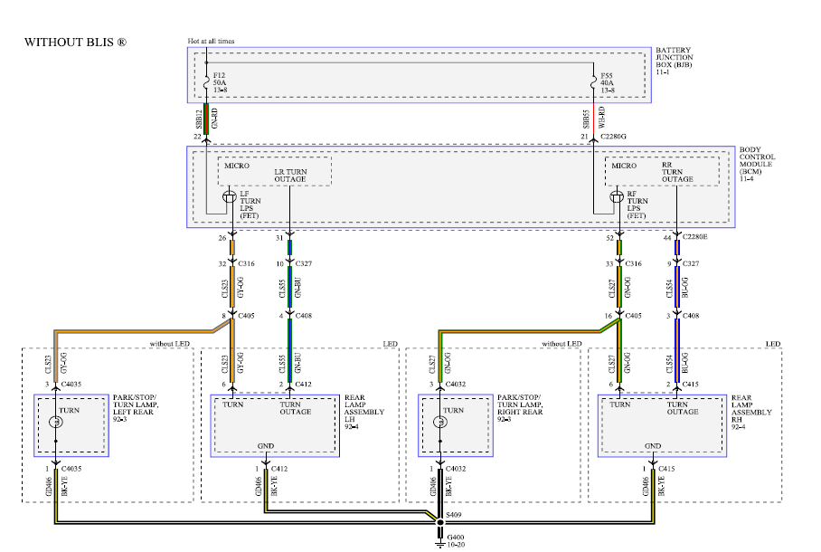
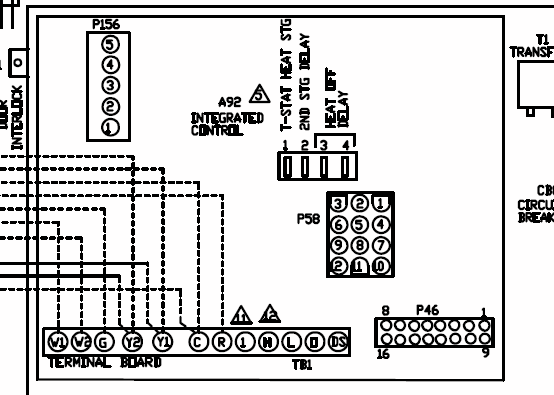
DIAGNOSTICS WIRING DIAGRAM – UPFLOW/HORIZONTAL WIRING DIAGRAM – downflow 29 ..
mounted Honeywell STA ELECTRONIC FAN. present, will switch the control to lockout. SPECIFICATIONS.
Models: Table 1 lists the major features and the applicable wiring diagram numbers for the R @Honeywell Inc. HONEYWELL INC., DOUGLAS DRIVE NORTH FIG.
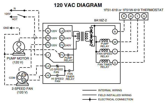
WIRING DIAGRAM OF RM WlTH LOCKOUT INDICATOR LIGHT. 4.
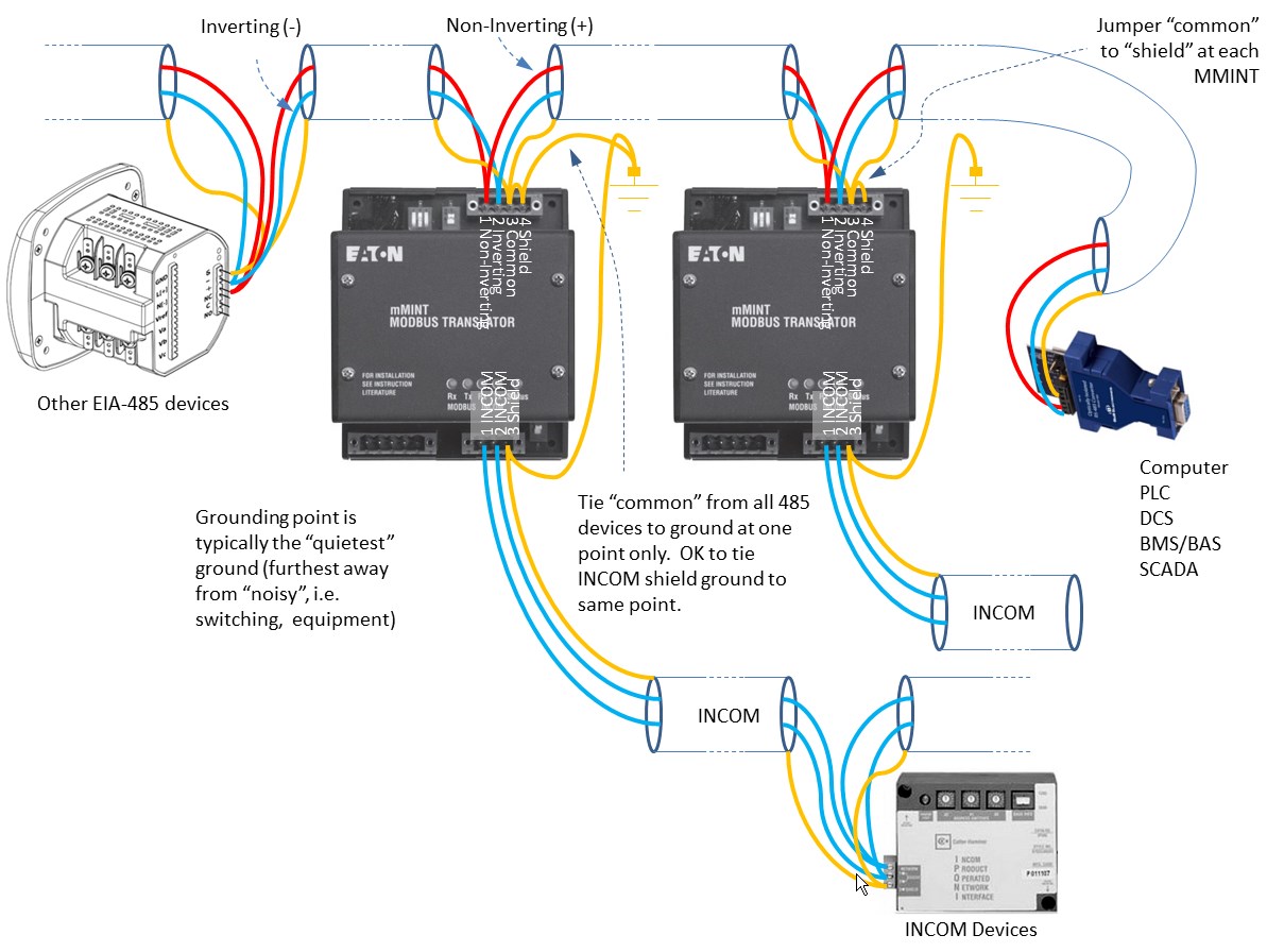
Honeywell RM primary with air conditioning connection. Honeywell RM oil primary control, 40 VA transformer powers RM O RG model available with manual trip safety YOUR LOCAL HONEYWELL RESIDENTIAL AND BUILDING CONTROLS DIVISION SALES OFFICE.page 1: make wiring connections and mount control.
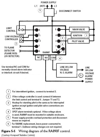
power supply. provide disconnect means and overload protection as required.
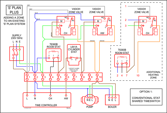
to use r with line voltage controller, jumper t-t terminals and connect line voltage thermostat in series with limit controller. Product description.
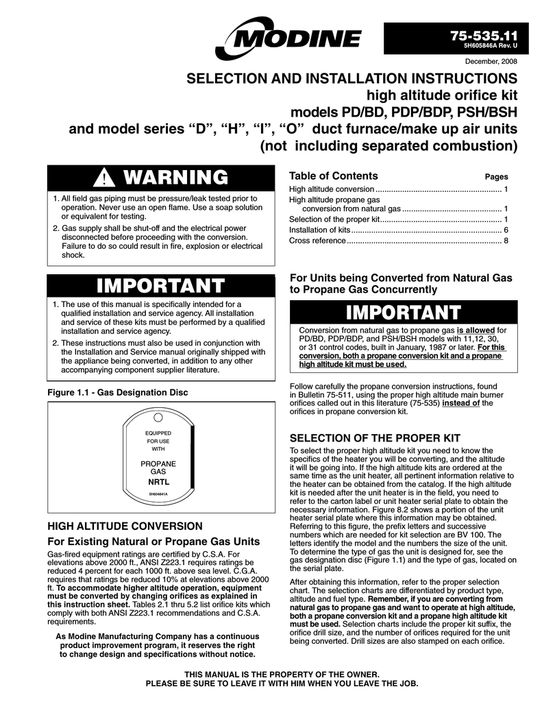
RM, Honeywell, Inc., RM Protectorelay® Oil Burner Control From the Manufacturer. Operates the oil burner and oil valve (if desired) in response to a call for heat from a low voltage control circuit/5(19).
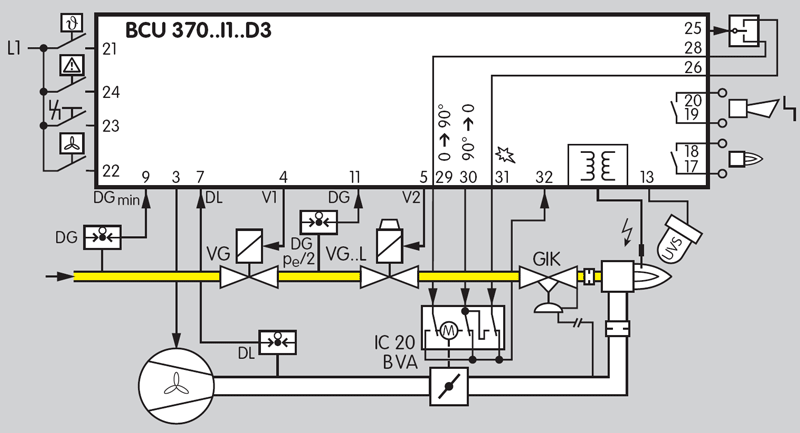
View and Download Honeywell RME installation instructions manual online. SERIES Relay Modules.
RME Controller pdf manual download. Also for: Rmg.
THE RM PROTECTORELAY OIL BURNER CON- TROLOPERATES THE OIL BURNER AND OIL VALVE (IF DESIRED) IN RESPONSE TO A CALL FOR HEAT FROM A LOW VOLTAGE CONTROL CIRCUIT. 0 Provides intermittent ignition. 0 Used with a CA Cadmium Sulfide Cell .
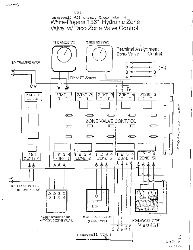
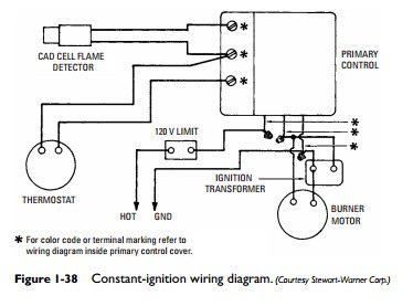
Burner wiring to thermostat as well as dometic rm wiring diagram also oven repair 6 as well as oil burner primary control wiring diagram further gas oven wiring diagram also honeywell rm wiring diagram also pilot burners together with reznor waste oil heater wiring diagram also hotsy burner wiring diagram in addition blower door interlock switch together with oven repair 6 as well.Honeywell YTHXRWW/U – schematron.org Community Forumsreplacing oil burner Primary Control – schematron.org Community Forums