
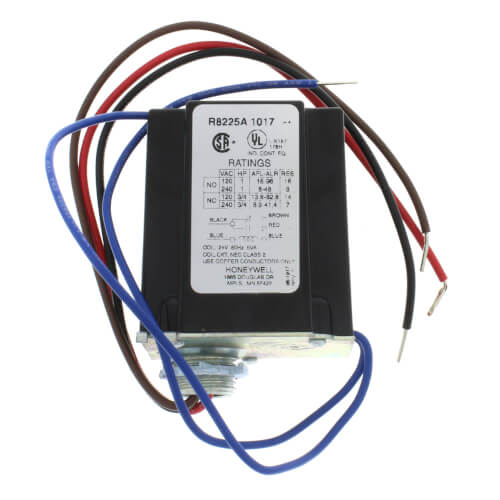
A Honeywell RA or equivalent DPST relay and transformer is required.
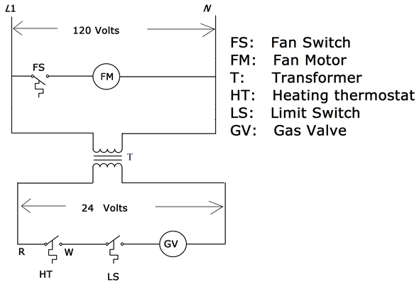
The high (Refer to Figures 11 & 12 for ladder and connection diagrams). Sequence of Relay 1R is the R mounted under the junction box. 4) A call for heat.
24 V Fan Relay with Dpst N.O. switching (Honeywell)
RD. R RA. RU. RF.
See Wiring. Diagram.
Honeywell Thermostat Wiring Instructions
Fig. 2.
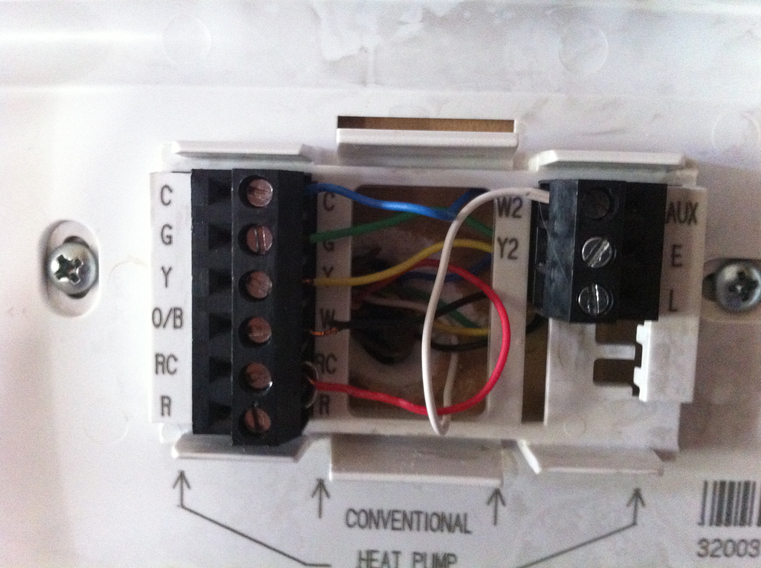
Fig. 3 .
Honeywell. Relays.
R R White Rodgers MARS. 8A J. H.
• • ©Honeywell Inc. • Form Number —2.
RA,B Relay. AFL.
ALR. Switching. Input Voltage (Vac).
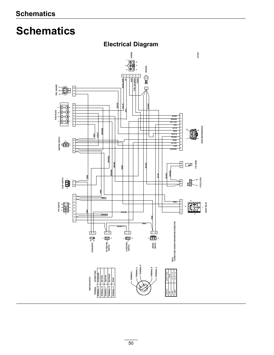
Diagram. RA. RB.
Technical Details
60 spdt After completing installation, use these instructions R ISOLATION. Ship Today! Learn more and buy online – Crown Boiler RB Relay. Crown Boiler RB Relay Honeywell RB Relay.
J. H.
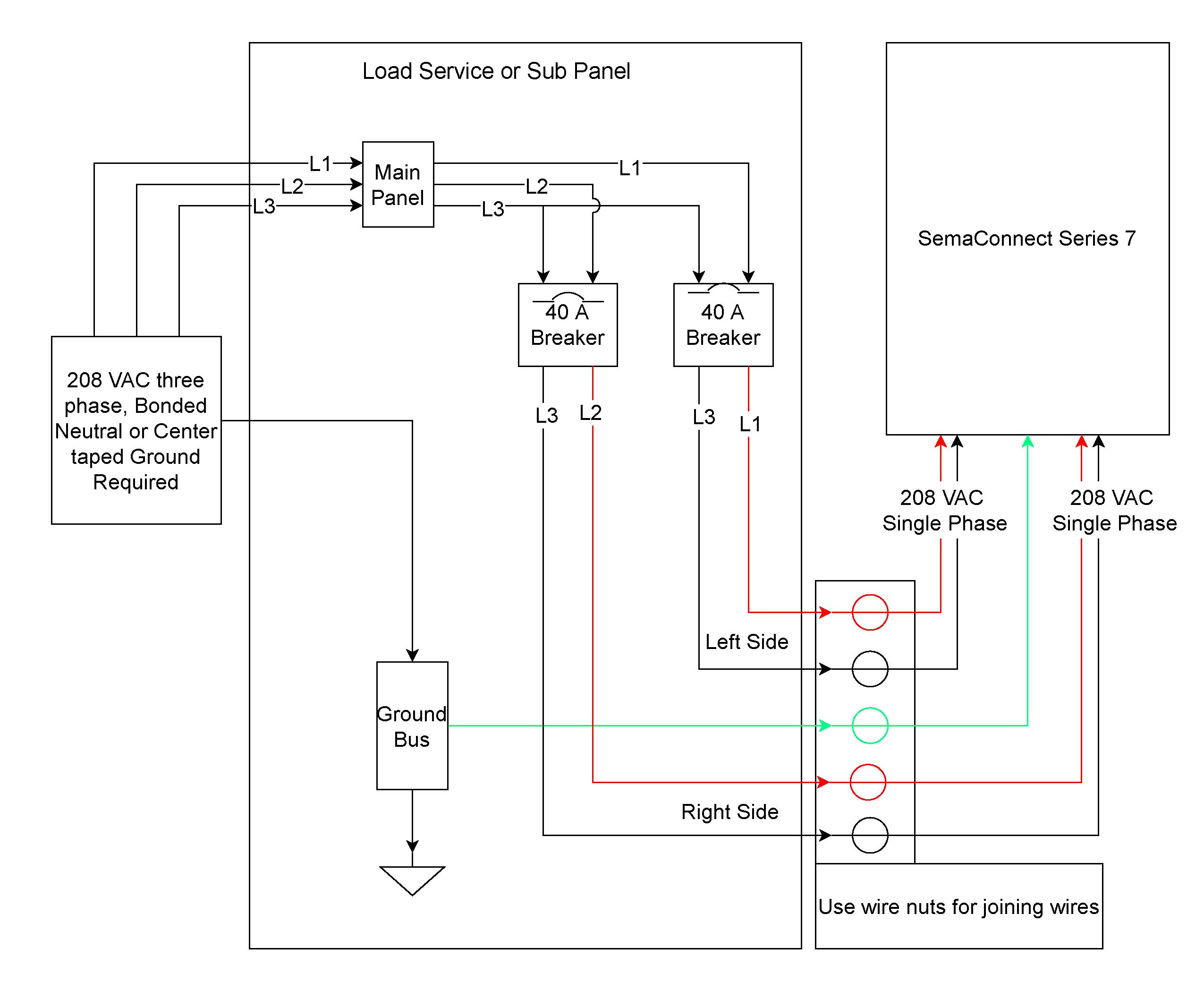
• • ©Honeywell Inc. • Form Number —2. RA,B Relay.
24 V Fan Relay with Dpst N.O. switching (Honeywell)
AFL. ALR.

Switching. Input Voltage (Vac).

Diagram. RA. RB.
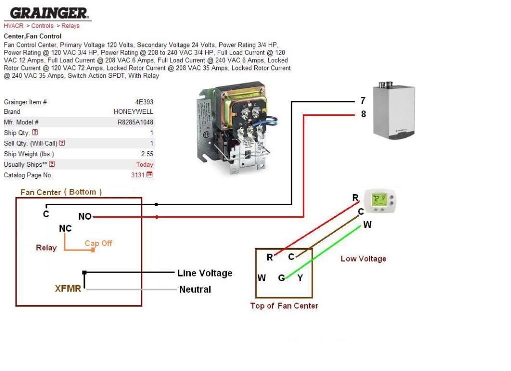
60 spdt After completing installation, use these instructions R ISOLATION.Molded terminal numbers and circuit diagram on top of relay provide easy identification for wiring and checking system operation. Untaped coil assures cooler operation. Laminated magnet construction for higher efficiency.
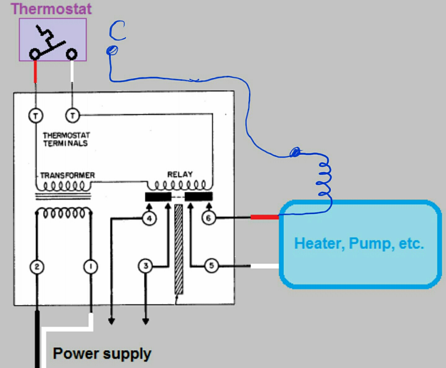
Base designed for easy replacement of . page 5: wiring diagrams.
Honeywell R4225; R8225 Fan Relay
la,e,j aquastat® relays t87f t87f t87f r r r relay pump pump pump (hot) la orange white c black burner ignition rg power supply. provide disconnect means and overload protection as required. control case must be connected to earth ground.
use grounding screw provided. ma b1 is 1/4 in. TA,B,C; TA,B,C Programmable Thermostats a Compatible with 2-wire Honeywell zone valves.
Isolating relay required for 3-wire thermostats for zone valves. Not location (check the appropriate wiring diagram). Refer to Figs. 5 through 7 for typical wiring diagrams.
Technical Details
• Molded terminal numbers and circuit diagram on top of relay provide easy identification for wiring and checking system operation. • Untaped coil assures cooler operation. • Laminated magnet construction for higher efficiency. • Base designed for easy replacement of competitive relays. • .
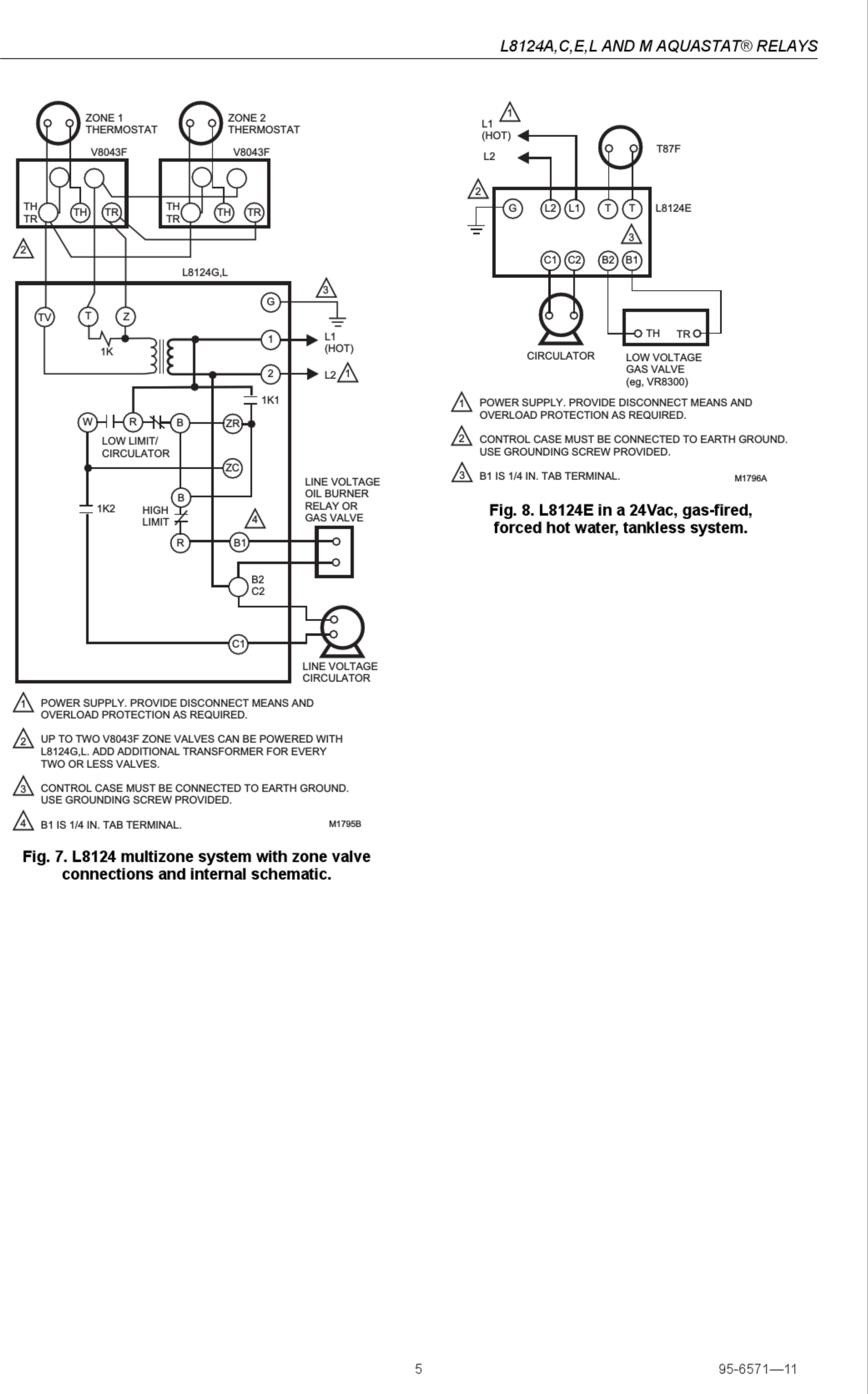
Molded terminal numbers and circuit diagram on top of relay provide easy identification for wiring and checking system operation. Open coil assures cooler operation.
Honeywell RM7895A Installation Instructions Manual
Laminated magnet construction for higher efficiency. Base designed for easy replacement of competitive relays.
Plug compatible with Steveco and Mars 24 V Fan Relay with Dpst N.O. switching (Honeywell) | schematron.orgFan Relay | Industrial Controls