Honeywell International Inc.
•. • All Rights Reserved.
INSTALLATION INSTRUCTIONS. 62 3 After completing installation, use these instructions.
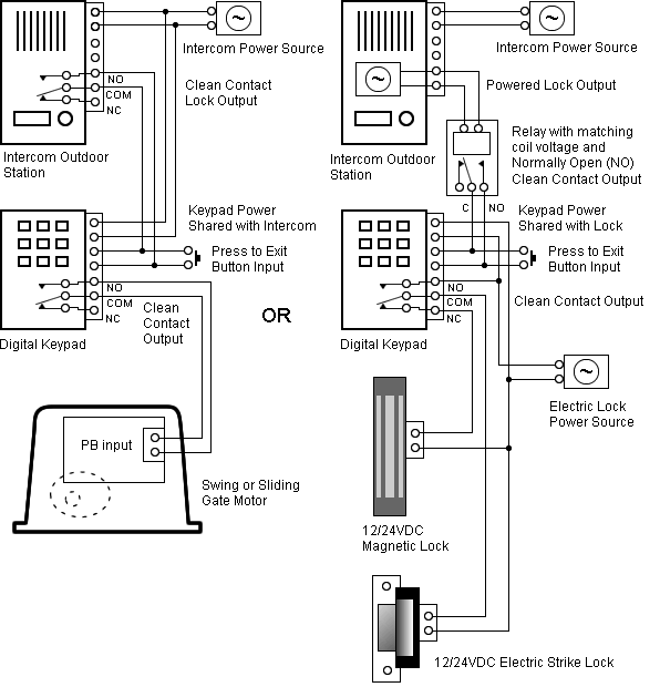
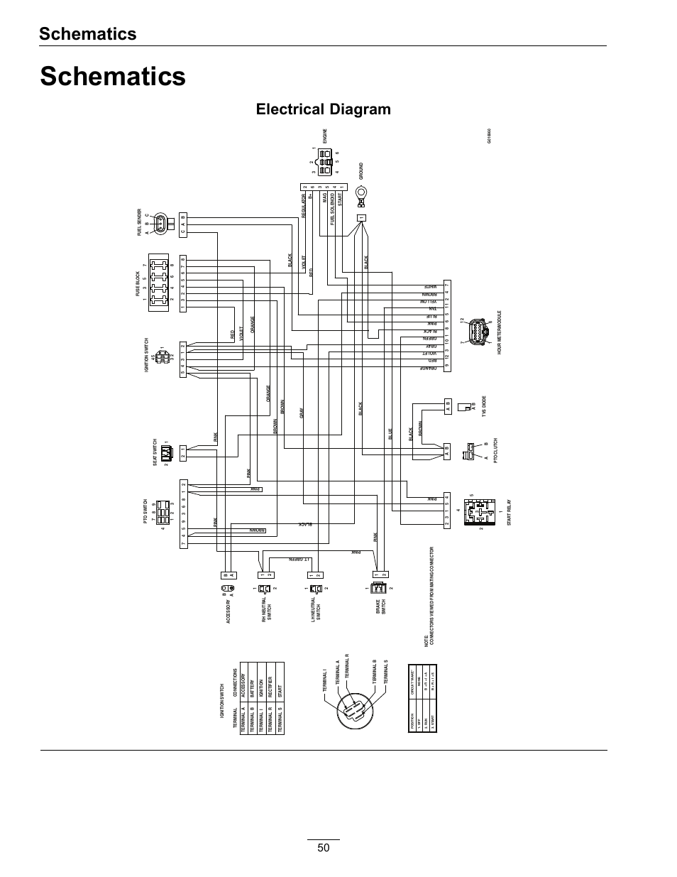
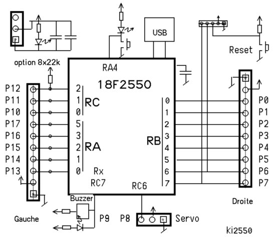
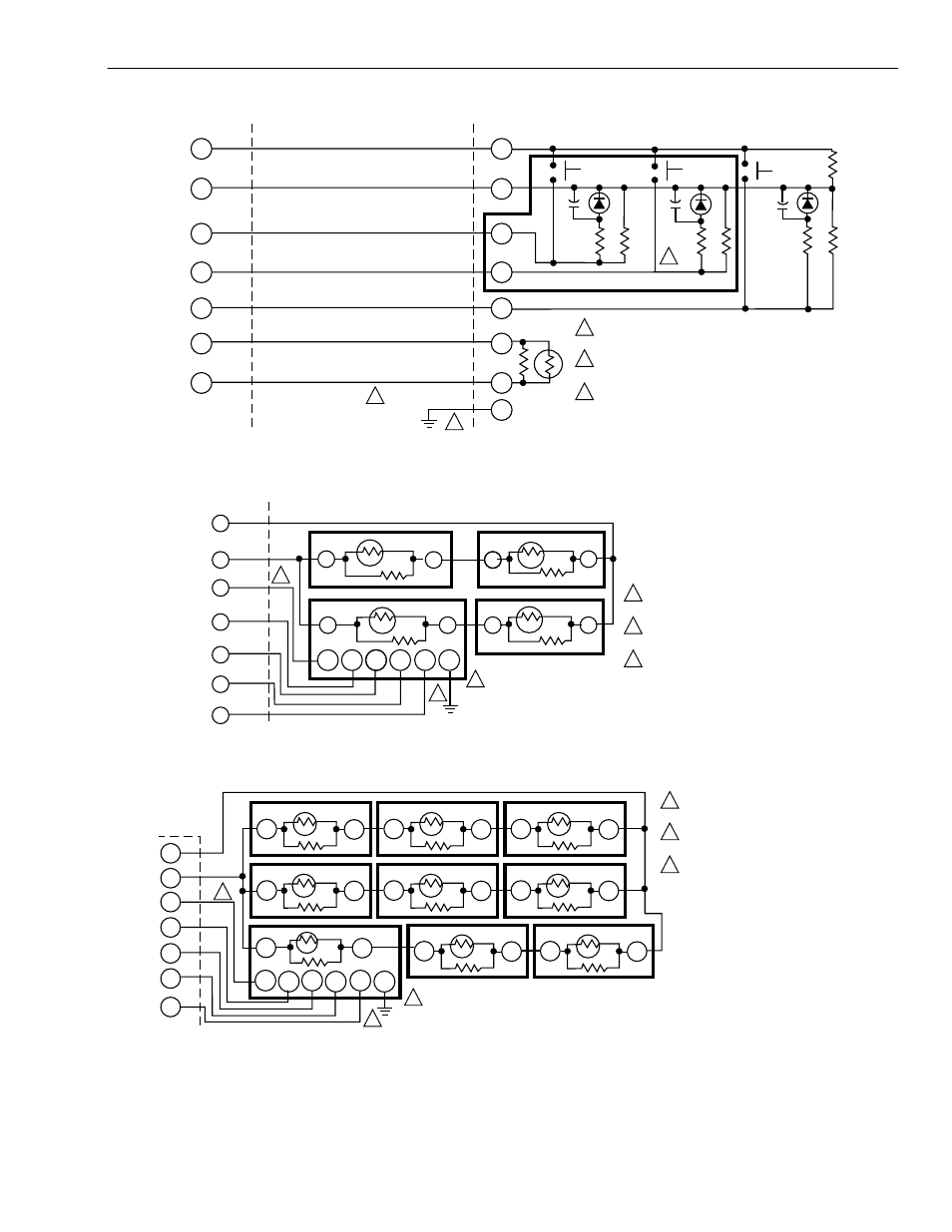
View and Download Honeywell QH system engineering online. 6 shows a typical wiring diagram for the TF/QH in a LonWorks® network. T EXCEL 10 CVAHU T BUILDING MANAGER EXCEL 15 W T Fig.
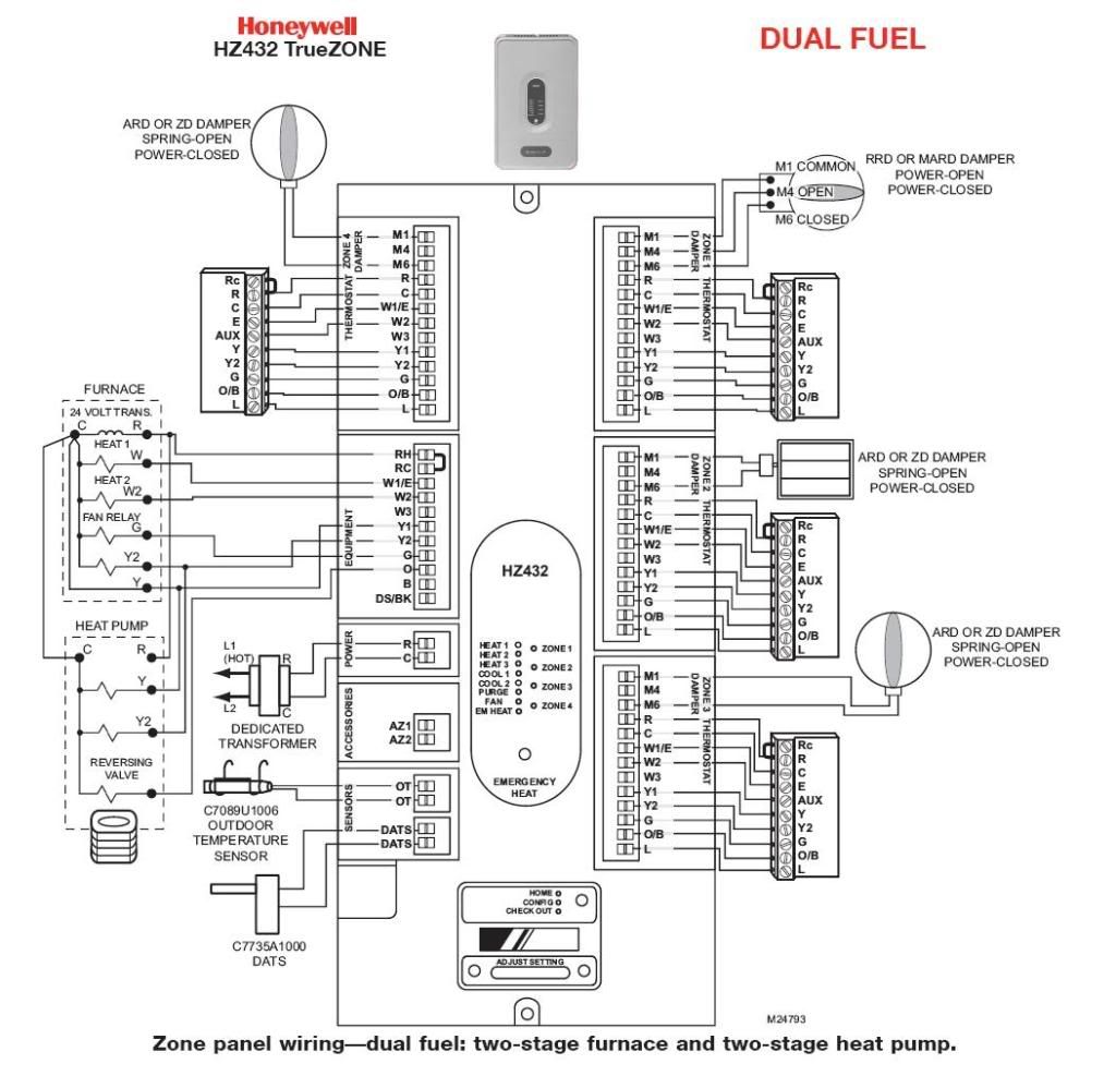
5. Typical wiring diagram for T used with T/Q Thermostat/ Subbase. Fig.
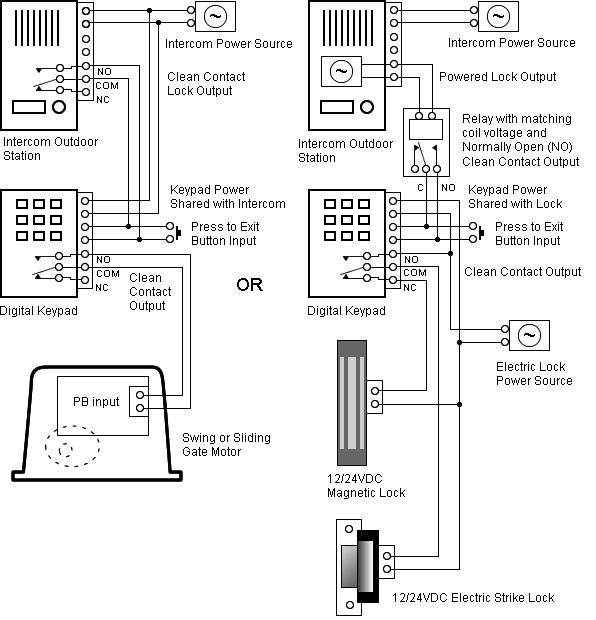
6. Wiring for T used in a four-temperature sensor averaging.
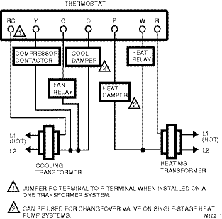
Thermostat Wiring Colors Code | HVAC Control
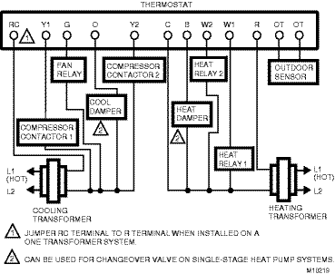
Step 4. Prepare Wiring Diagrams.
. T MODEM.
MODEM. MB.
Understanding and Wiring Heat Pump Thermostats with AUX & Em. Heat! Terminals, Colors, Functions!
EXCEL CVAHU. Back Select.
1. 4. 8 12 16 .
Honeywell AK (US only). I am trying to replace a Honeywell thermostat T with a T The T has two T terminal wires, but the T has – Answered by a verified HVAC What is the wiring diagram for a Honeywell RUHoneywell QA Installation Instructions Manual.
Commercial thermostat subbases. Also See for Honeywell QA.
Honeywell TD Product Data 40 pages. Five TG Sensors providing temperature averaging network for MOUNTING T/Q Thermostat/Subbase.
Honeywell Q7300H System Engineering
SCREWS M SUBBASE LEDS Fig. 7.
Mounting the subbase. Programmable Commercial Thermostats and Subbases J.
Honeywell Q7300A Installation Instructions Manual
A. • Rev. • • ©Honeywell Inc. The T, T Thermostats and Q Sub-bases control commerical single zone heating, ven- tilating and air conditioning (HVAC) equipment.
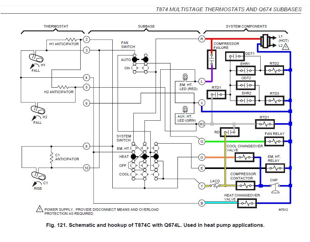
with the letter or number on the wiring terminal as the wire is . installation guide honeywell international. in wall electric heater thermostat wiring diagram in wall electric heater thermostat wiring diagram also choosing the right thermostat to her with hvac split system wiring diagram furthermore geyser honeywell thpa wiresaver wiring module for honeywell thpa wiresaver wiring module for.
everything from wiring diagrams to guide specs • Data trending for use in troubleshooting Honeywell thermostat that uses both an outdoor air sensor and indoor sensors/wall modules for heat pump control applications. (TB, D, H and TF) Equipment Protection.
M Fig. 5. Typical wiring diagram for T used with T/Q Thermostat/Subbase.
T/Q TC TC ONLY ONE T ALLOWED PER SYSTEM. Page 6: Operation.
Warmer or Cooler keys. 3 Hour Occupied override. In response, the T/Q sends a signal back to the T to turn on the 3 Hour 5.Thermostat wireing diagram/honeywell t – FixyaHONEYWELL QA INSTALLATION INSTRUCTIONS MANUAL Pdf Download.
