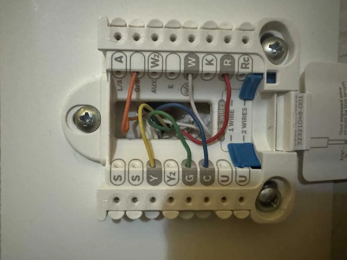
If you’re looking to properly install or troubleshoot a 6-wire system, it’s crucial to connect each terminal correctly. Each connection serves a specific function, and any misplacement can lead to system malfunction or inefficiency. Here’s a straightforward guide to help you ensure a flawless setup.
1. Identify the Common Terminal (C): This is the reference point for the system’s power supply. The C terminal connects to the power supply, allowing the device to function without relying on batteries.
2. Heat and Cool Control (R and Y): The R terminal is used for the heating source, while Y controls the cooling system. Make sure each is wired to the corresponding components for smooth heating and cooling operation.
3. Fan Control (G): The G terminal operates the fan. When wiring, connect it to ensure the fan turns on and off with the system’s temperature regulation cycles.
4. Auxiliary Heating (W2): This terminal is crucial for multi-stage heating systems. It activates additional heating elements when the primary unit can’t meet the set temperature.
With these steps, your installation should be ready to handle both heating and cooling effectively, ensuring consistent performance from your system.
6-Connection Setup Guide
For a system with six terminals, follow this configuration: R connects to the red lead for power. The C terminal, often blue or black, should be linked to the common conductor, ensuring consistent voltage.
The cooling control goes to the Y terminal, typically yellow. The heating relay is assigned to the W terminal, which is usually white. For fan operation, connect the G terminal, often green, to the fan circuit.
If additional features are involved, like heat pump systems, the O/B terminal may be used. This helps control reversing valves, essential for regulating the heating and cooling processes in certain setups.
After ensuring all connections are secure, double-check the accuracy of each one, as an incorrect setup could lead to operational issues.
Tip: Always ensure that the power is turned off before starting any installation process to avoid electrical hazards.
Understanding the Layout for a 6-Conductor System
Ensure that each terminal is properly matched with its corresponding signal to prevent malfunction. The six conductors typically represent the following functions:
R – Connects to the power supply from the HVAC unit, providing the system with a constant voltage source.
C – Serves as the common terminal, completing the circuit. This conductor is necessary for powering the system’s display and other features.
Y – Controls the cooling cycle, signaling the system to activate the compressor when needed.
W – This conductor is linked to the heating element, triggering activation of the heat mode.
G – Connects to the fan, allowing it to run in either heating or cooling mode depending on the system’s demands.
O/B – This terminal is used for systems with a heat pump, switching between heating and cooling modes. Ensure correct polarity when connecting to avoid operational errors.
Accurate placement of each conductor is essential for optimal function. Refer to the unit’s manual for any adjustments or specific terminal configuration for different models.
Connecting a 6-Wire Control to Your HVAC System
For a smooth connection of a 6-wire control to your HVAC system, follow these steps. The terminals to focus on are typically marked R, C, W, Y, O, and B. Begin by attaching the red lead to the R terminal, which powers the system. Then, connect the C lead to the C terminal to complete the circuit for power. The white wire connects to W for heating control, while the yellow lead goes to Y for cooling functions.
The O wire is essential for reversing the system if you have a heat pump. Attach this to the O terminal, which controls the heat pump’s reversing valve. Finally, connect the blue wire to the B terminal for the backup heat control, if applicable.
Ensure the connections are secure and that the correct terminals are used for each lead. A misconnection can lead to malfunctions, so double-check each one. After wiring, power up the system and test its functionality by switching between heating and cooling modes. Make sure that each function responds as expected.
For best results, always consult the manufacturer’s manual for any specific wiring nuances or instructions that may apply to your particular model.
Troubleshooting Common Issues with 6-Conductor Control Systems
When the system fails to operate as expected, start by checking the connections for any signs of loose or misconnected terminals. A common problem involves a poor connection at the control board or terminals. Ensure all terminals are securely fastened and that no wires are frayed or damaged.
- Non-Functioning Heat or Cool Mode: Confirm that the ‘R’ and ‘C’ terminals are properly connected. If these terminals are not linked, the device will not receive the necessary power supply to operate in heating or cooling mode.
- System Not Turning On: Inspect the common conductor (C) and its link to the control panel. Without a continuous C wire, power cannot be supplied to the system, leading to non-operation. If absent, consider installing a jumper or ensuring a proper connection.
- Blank Display: A blank screen may be a sign of a power issue. Double-check the connection at the ‘R’ terminal and the primary power source. Ensure there is no interruption between the unit and the power supply.
- Fan Running Continuously: The fan control wire, typically connected to the ‘G’ terminal, may be improperly configured or malfunctioning. Verify the setup and replace any damaged components.
- Erratic System Behavior: If the system is switching on and off unexpectedly, inspect the system’s voltage. Unstable voltage can cause improper signal transmission, leading to irregular operation.
For troubleshooting, follow a methodical approach to test each connection individually. Using a multimeter can help detect voltage irregularities at each terminal to ensure everything is functioning properly. If issues persist after checking connections and power, the device may need further inspection or component replacement.