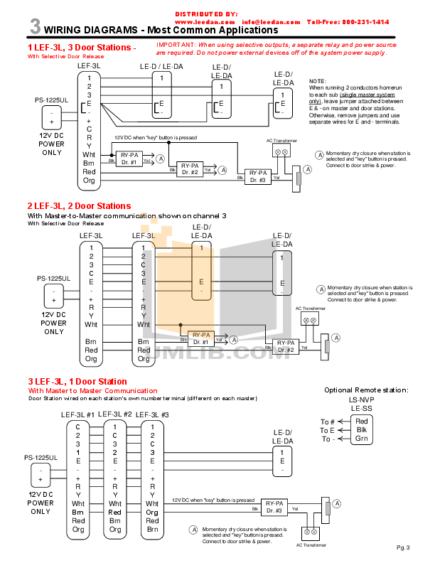
Hi all I have read the wiring diagram and suggestions regarding converting from Honeywell st to Stc timer but all guidance describes.
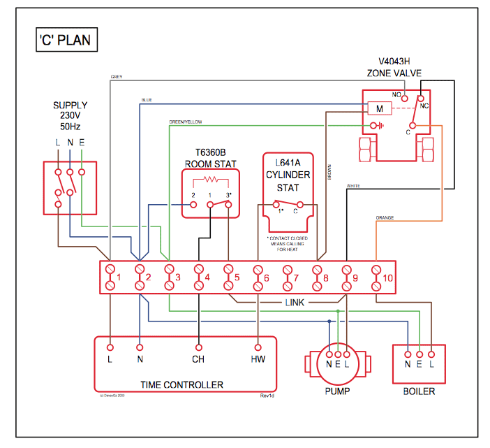
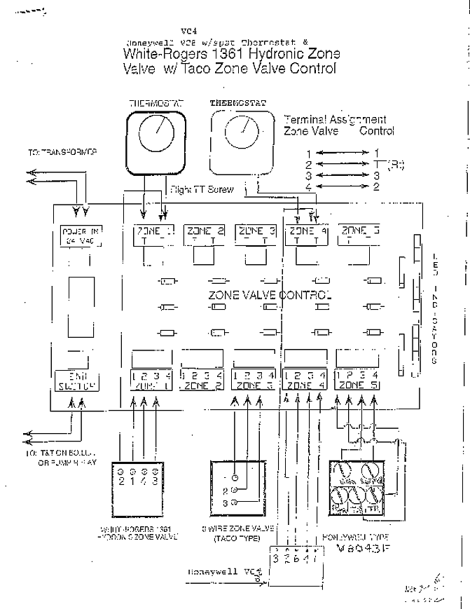
Get free help, tips & support from top experts on honeywell st related issues. not my heating side according to wiring diagram terminals on ST ST ST L..
Honeywell ST699 to Hive
While it appears the ST is a timer that connects to a thermostat. Honeywell ST to Hive Bypassing the thermostat, removing it totally from the wiring centre rather than bridging it at the actual stat took That doesnt look like a hive diagram.
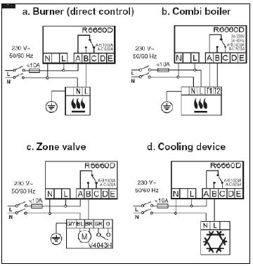
. Replacing an old Honeywell ST Timer?. Get free help, tips & support from top experts on honeywell st related issues.
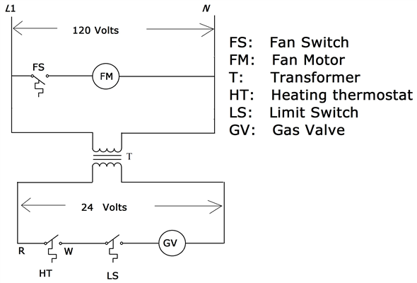
not my heating side according to wiring diagram terminals on ST ST ST L.. While it appears the ST is a timer that connects to a thermostat.
APPLICATION. The ST and ST are time control programmers that can be used as replacement programmers on gravity primary or fully pumped systems.Jul 21, · Would I need to replace it with a Honeywell model or are all the wires like for like?
Is it as simple as looking at a wiring diagram for the ST and attaching to . The ST time control programmer can be used as a replacement programmer on gravity primary or fully pumped systems.
The ST has a proven easy to use design. The front panel of the programmer will fit to the same backplate.
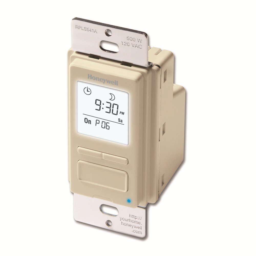
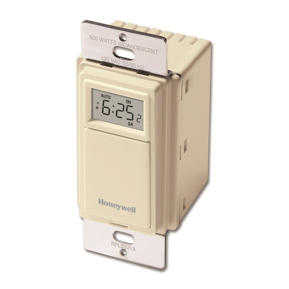
Programming the timing sequence is straightforward, using the top slider switch and [+] and [-] buttons. The Honeywell RPLSA/U ECONOSwitch Programmable Light Switch Timer (White) can help save you money while adding a level of convenience and safety to your home.
ST ELECTRONIC DUAL ZONE TIMER 3 EN0R R0 ROOM THERMOSTAT BOILER PUMP CLOCK ST FUSE WIRING Cable entries can be made through the opening in the rear of the subbase, or via the three surface entry break-outs in the top and two sides of the wallplate. See fig. 2 The ST is designed for fixed wiring only and must be.
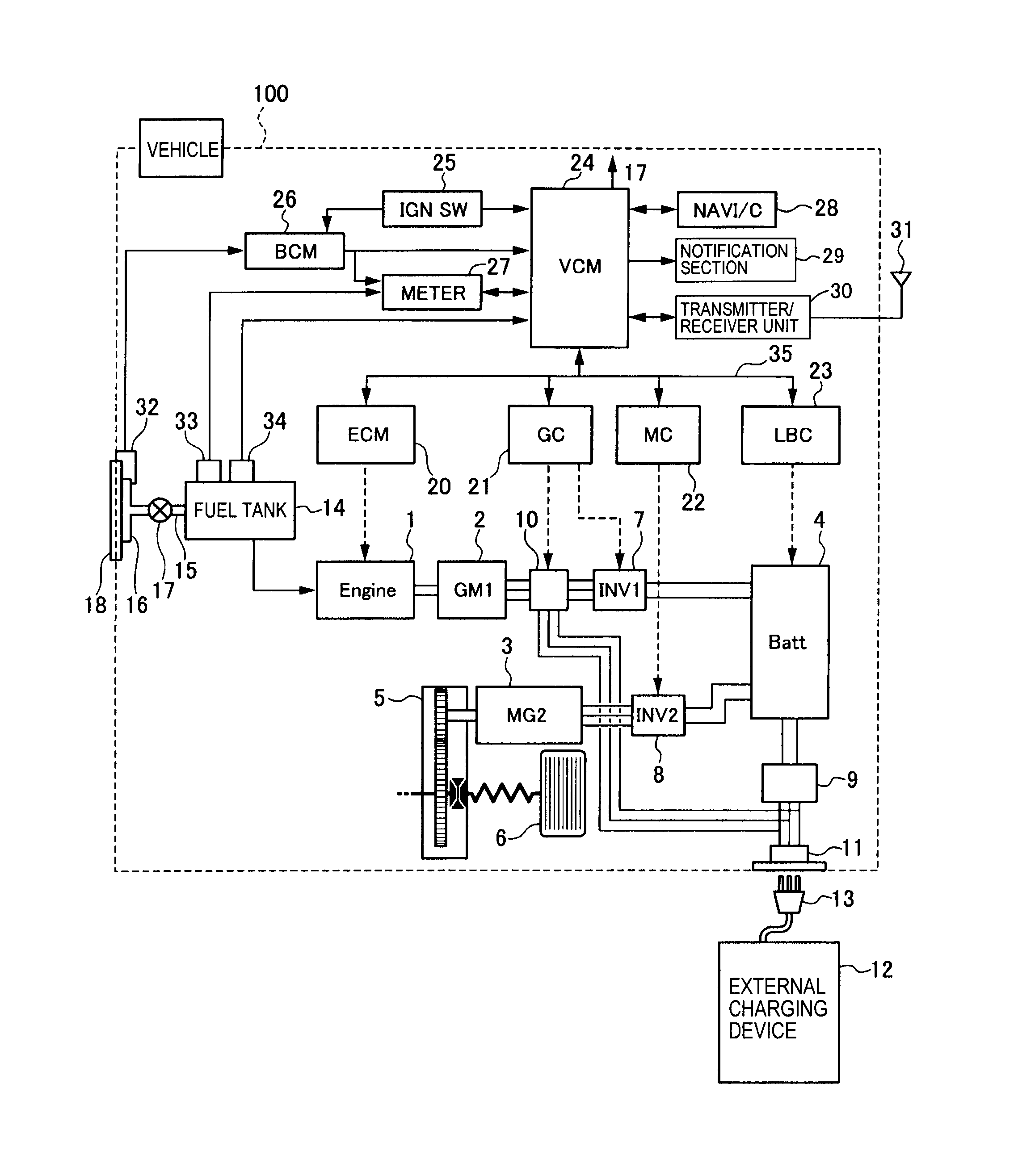
Feb 20, · In trying to diagnose the fault i looked at several wiring diagrams for the st, one of which counted from right to left not left to right, leading me to think the link wire should be on terminal 4 not terminal 5, i hope you see what i mean? the wiring diagram is the “honeywell a”.pdf.Honeywell St Wiring Diagram – Wiring Diagram And SchematicsReplacing an old Honeywell ST Timer? | DIYnot Forums
