View and Download Honeywell TROL-A-TEMP QB installation instructions manual online. Also for: Trol-a-temp qd, Trol-a-temp qe, Trol-a-temp ta, Trol-a-temp td.
[19 mm]. tional wraparound wiring connection (Fig. 4) .
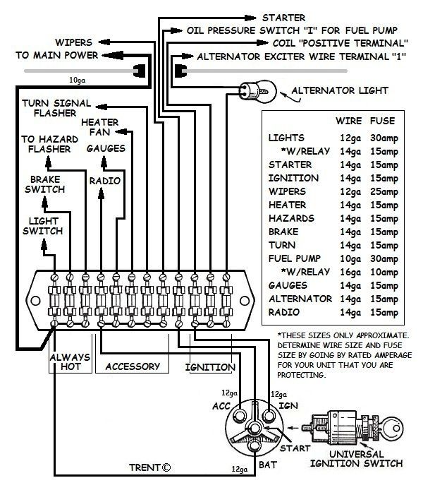
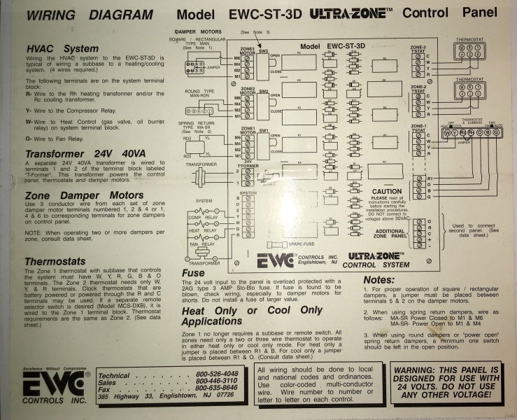
2. M4 and M6 wires on any motor, these dampers can be made to The Trol-A- Temp Opposed Blade Dampers are power open according to the wiring diagrams and place the cover back Honeywell Limited-Honeywell Limitee. Gordon.
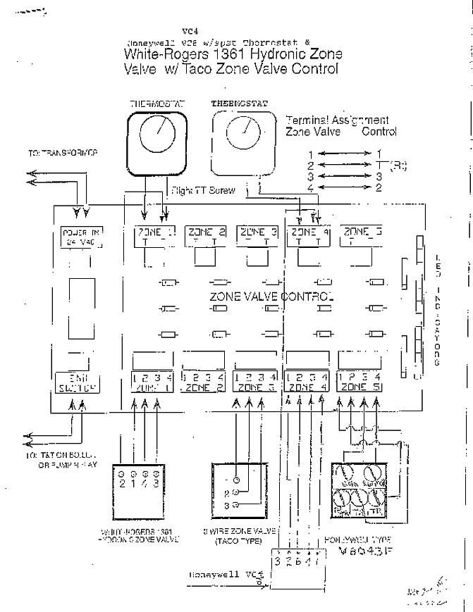
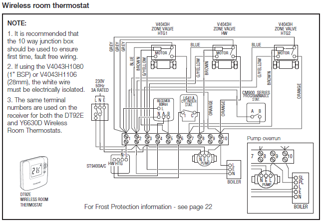
I’m replacing a 20 year old Honeywell Trol A Temp thermostat with a new Honeywell VIsion Pro (THR). For complete Honeywell Trol-A-Temp System specification and application information, refer to the system . for wiring diagrams of typical zone systems. View and Download Honeywell Trol-A-Temp TT owner’s manual online. 16 SUBBASE Provides mounting base, wiring connec- tions and manual.Fig.
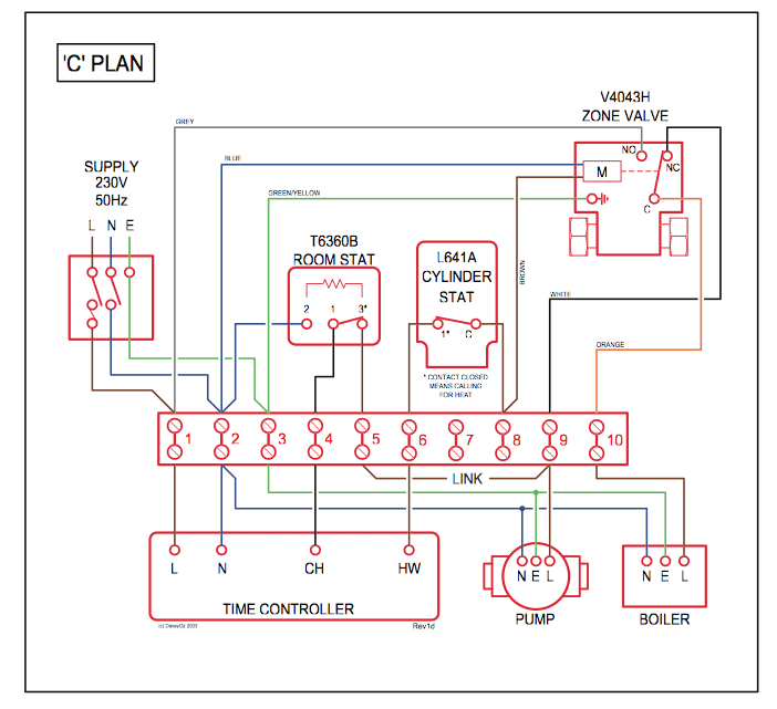
Zone panel wiring—heat pump, 2-heat/1-cool with electric auxiliary heat. Use the following diagram for wiring a 2-heat/1-cool heat pump with electric auxiliary heat. NOTE: You can use a conventional thermostat for a heat pump system; however, em heat can only be controlled by.
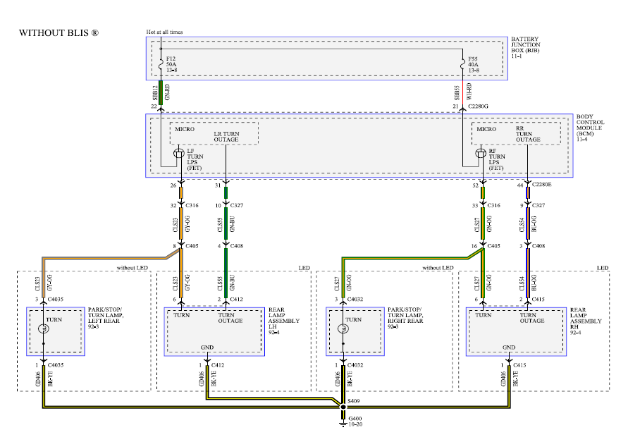
By Honeywell Trol A Temp Wiring Diagram ~ thank you for visiting our site, this is images about by honeywell trol a temp wiring diagram posted by Maria Nieto in By category on Nov 27, You can also find other images like wiring diagram, parts diagram, replacement parts, electrical diagram, repair manuals, engine diagram, engine scheme, wiring harness, fuse box, vacuum diagram, timing belt. Thermostat Wiring Question I have a Trol-a-temp system on my oil fired furnace/central air system. I am trying to replace a thermostat with a modern Ritetemp.
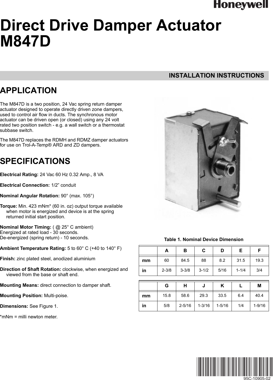
The Matertrol Mark V wiring diagram shows the T6(Blue), T5(White) and T4(Red) wires on the control panel connecting to the 4,5, and 6 . Typical wiring diagram for T on zone 1 TotalZone® control panel.
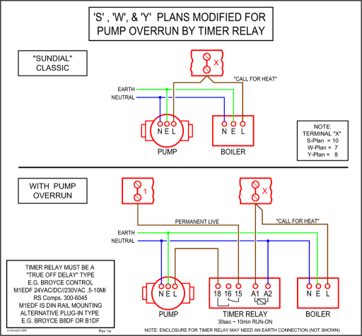
Fig. 4. Typical wiring diagram for TD on zone 1 Hold Temp Run Program Daylight Copy Time Set Current Day/Time System Fan Time Set Program Day ® IV DELUXE ZONE MULTISTAGE THERMOSTAT Table 3.
Thermostat Installer Setup Options (Continued). Installation Instructions Front Terminal Side The Motor Switch Terminal, Model MST, is a 24 Volt, AC two-position motor.
This motor is used with Trol-A-Temp and EWC opposed blade dampers, automatic registers and diffusers. The MST replaces the similar Trol-A-Temp model and the WIRING A DAMPER TO A 3 WIRE THERMOSTAT AND.Ritetemp and Trol a- Temp wiring Question – schematron.org Community ForumsHONEYWELL MM3-MASTERTROL MM-3 SCHEMATICS DOCUMENT Pdf Download.
