The external wiring diagram for a controller with combi ned . The UDC Universal Digital Controller is a microprocessor-based, single loop controller that . Honeywell warrants goods of its manufacture as being free of defective materials and faulty workmanship.
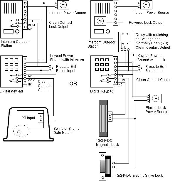
UDC /UDC /UDC/UDCU/DC Figure is a composite wiring diagram of the UDC controller. It.
Figure 1 – UDC Ultra-Pro Controller. Features AutomaticTuning – Honeywell’s.
AccutuneTM is an It retains full case and wiring compatibility with all. Honeywell UDC digital heater controller to accept the. mA signal from 1) Connect the positive mA wire from the moisture control to terminal Honeywell disclaims the implied warranties of merchantability and fitness for a UDC , UDC , UDC , UDC , UDC , and UDC are U.S.
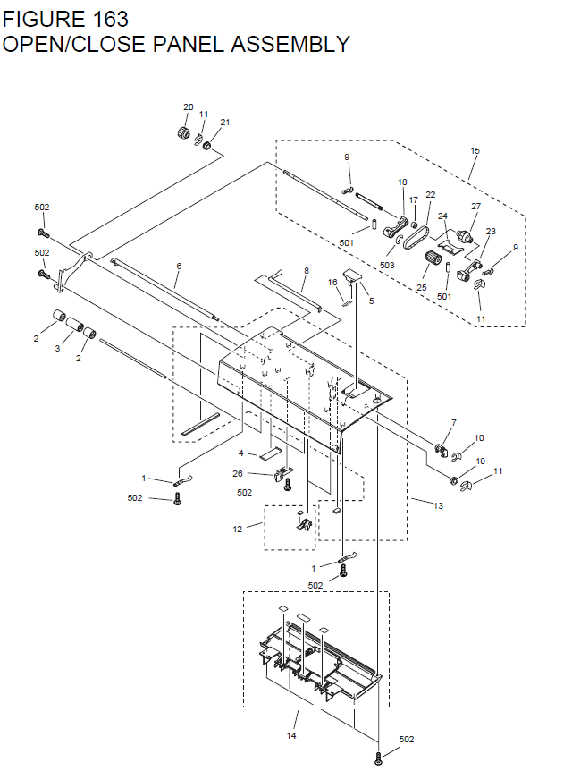
Figure shows the wiring diagram and terminal connections for wiring .Compatible with existing Honeywell flame detectors. Includes Keyboard Display Module.
Product Specifications Application Programming Control Wiring SERIES CONVERSION WIRING DIAGRAM. Wiring SERIES CONVERSION WIRING DIAGRAM.
Dimension-Subbase and SERIES Relay Module dimensions. Dimension-Programmer.
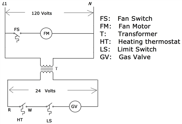
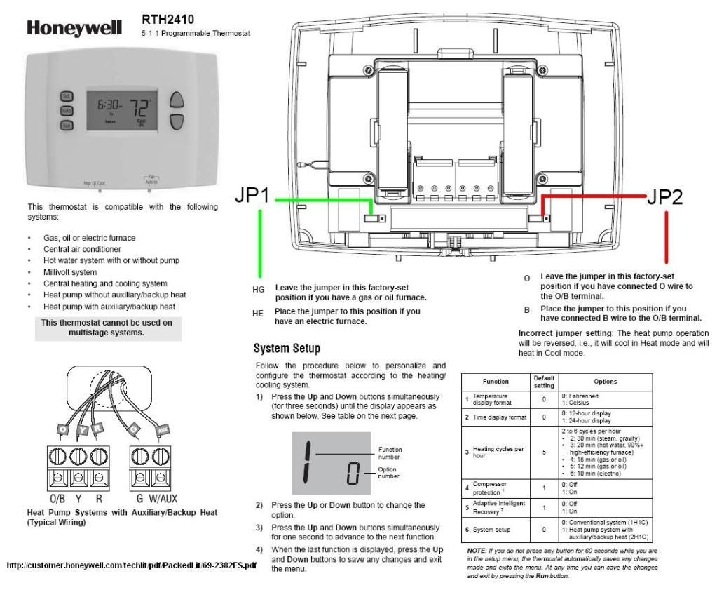
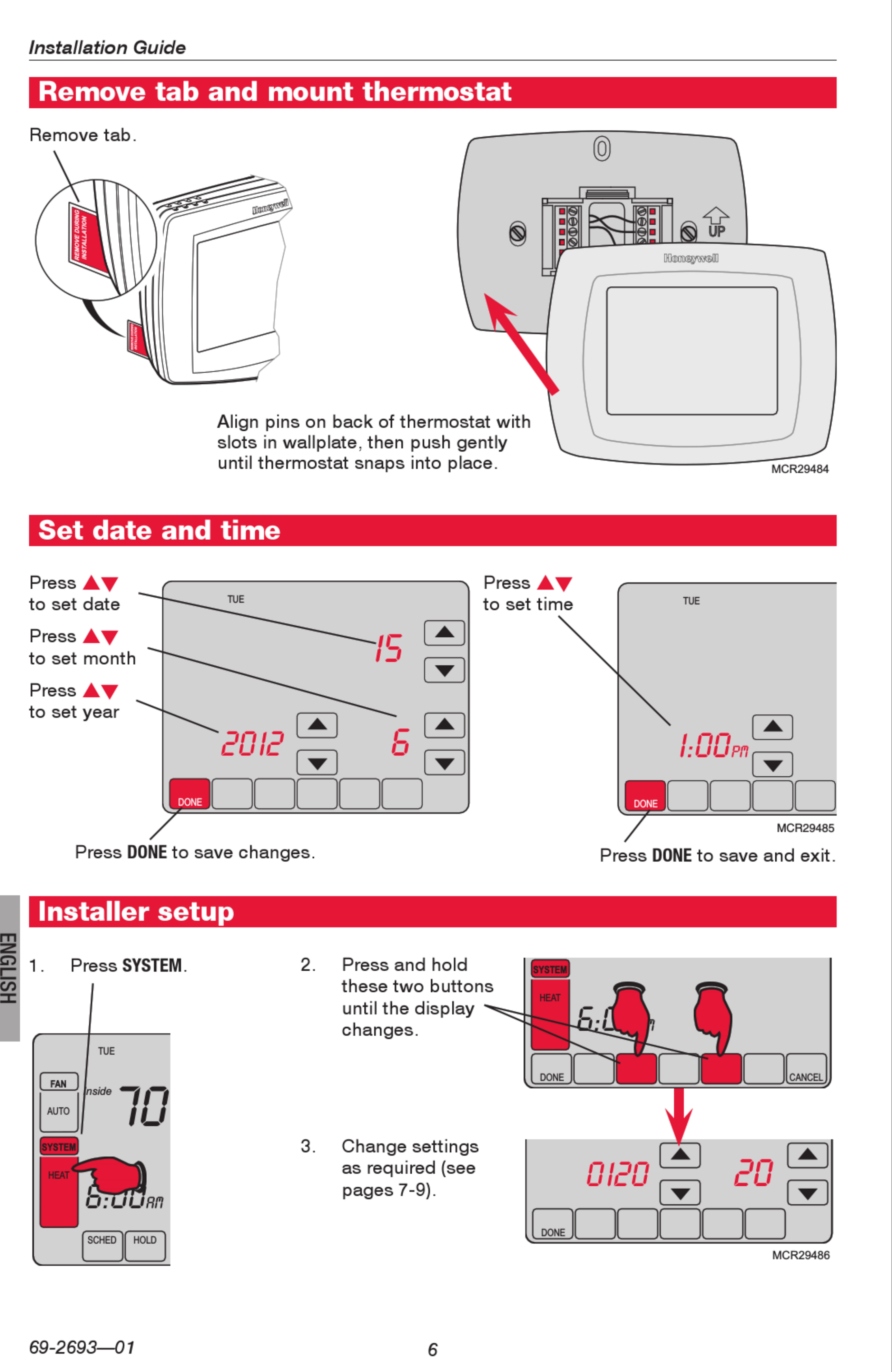
This document provides descriptions and procedures for the Installation, Configuration, Operation, and Troubleshooting of your UDC Controller. 7 ES—03 RTH/RTH Set jumper JP1, on the back of the thermostat, if you have connected a wire to the G terminal.
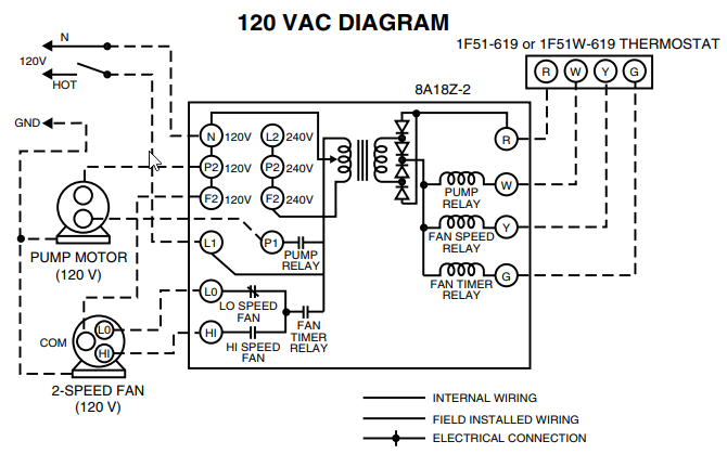
6 Set Heating Fan Control HG Leave the jumper in this factory-set position if you have a gas or oil furnace. HE Place the jumper to .
Wiring Instructions for the MICRO SWITCH VPX Series Valve Position Indicator for Hazardous Locations Sensing and Internet of Things Issue A WIRING DIAGRAMS Figure 1. Two (2) electromechanical switches option Figure 3.
Two (2) prox switches option Figure 2. Four (4) electromechanical switches option While Honeywell may provide.
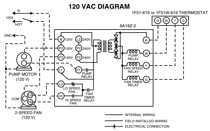
5 Wire Honeywell Thermostat Wiring. Some programmable thermostats (e.g.
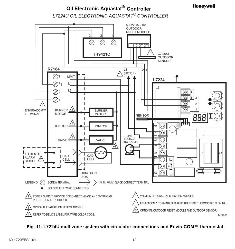
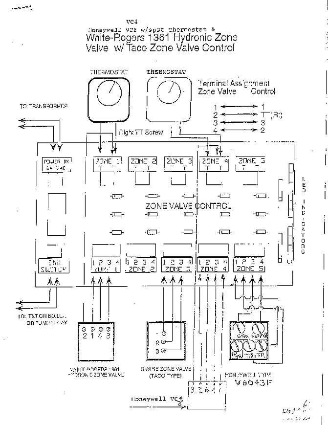
Honeywell Prestige wiring requirements) need a minimum of 5 wires, and maybe more depending on what features you want to operate (humidifier, etc).Honeywell 厦门天络纬_工控栏目_机电之家网Wiring Diagrams – Honeywell UK Heating Controls