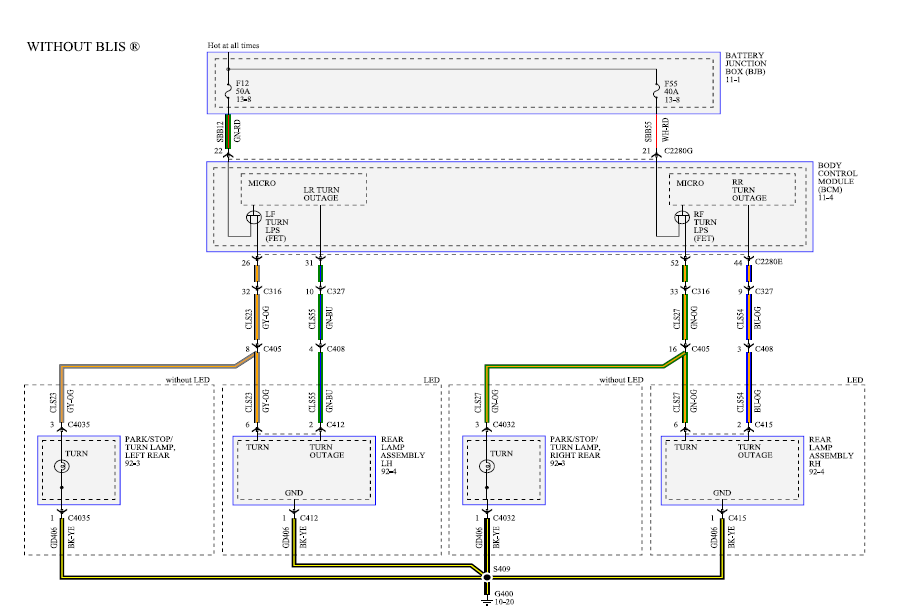
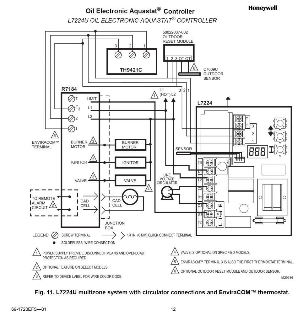
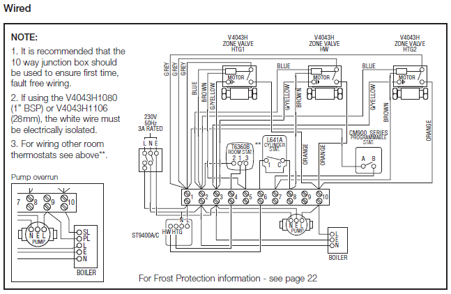
ve u rh customer honeywell com honeywell zone valve Honeywell Vf Wiring Diagram, Honeywell Vf Wiring. Some stuff about Zone Valve Honeywell zone valve control honeywell · hydronic zone valves honeywell · zone valve wiring diagram honeywell · autozone lift.
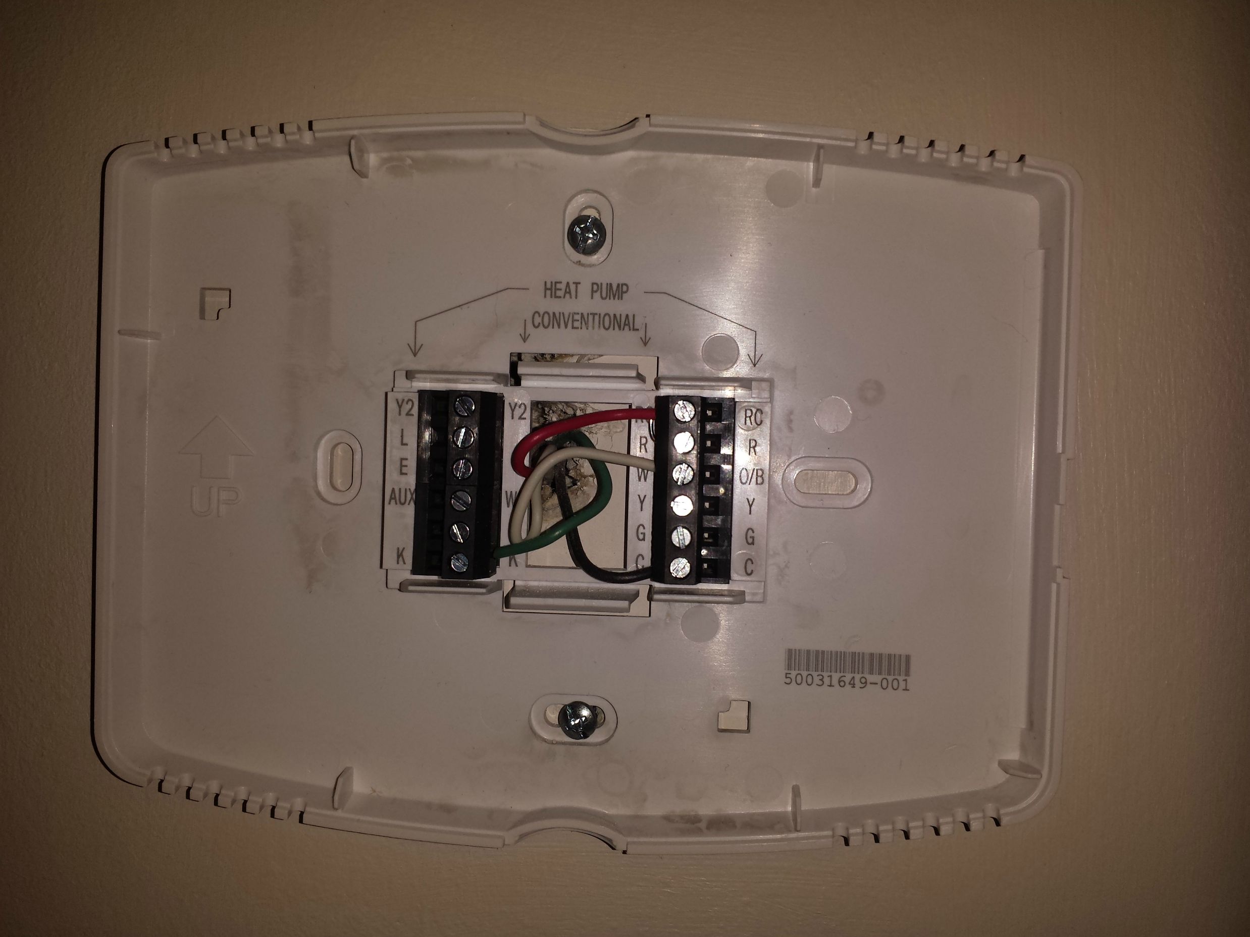
Screw terminal wiring panel for added convenience. • Built-in auxiliary contacts to Selection Chart.
** valves are Cv; Honeywell and Erie valves are Cv. 13V 1/2″.
Inverted VE VTG13A02A. 13N 1″.
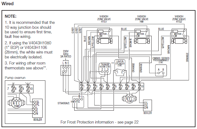
NPT . 3 days ago Wiring diagram how to install rhgalericannacom jab replacement motor Ve Honeywell Ve 3 4\” Npt Connection Zone. Ve U RTHB Wiring Honeywell Ve Zone Valve Wiring.
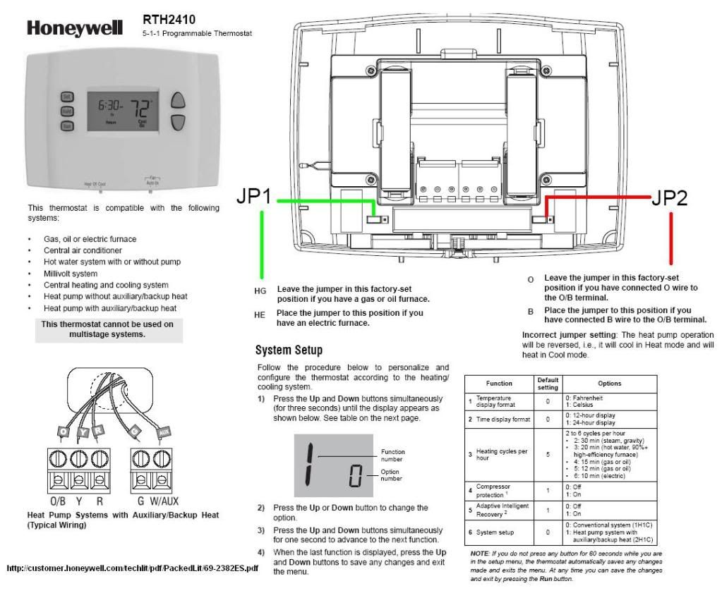
Source. ve u honeywell rthb wiring diagrams wiring.Wiring for low-voltage two-position control Actuator Wiring Diagrams Direct Coupled Actuators – Spring Return Models.
Direct Coupled Actuators – Spring Return Models Wiring for (0) Vdc proportioning controller operating multiple actuators M 3KΩ 0°° OR + 90°-0° OR N/A. Wiring Instructions for the MICRO SWITCH VPX Series Valve Position Indicator for Hazardous Locations Sensing and Internet of Things Issue A WIRING DIAGRAMS Figure 1.
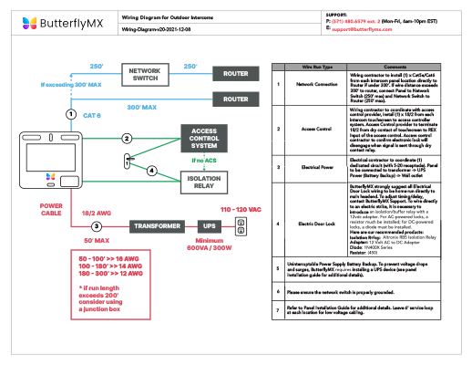
Two (2) electromechanical switches option Figure 3. Two (2) prox switches option Figure 2. Four (4) electromechanical switches option While Honeywell may provide.
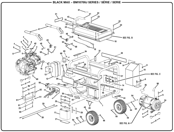
Wiring-Wiring Honeywell VF to Taco system. Wiring-Wiring VE to Dole system and Flair System.
Wiring-Wiring VF to Dole System and Flair System. Wiring-Existing Dole system.
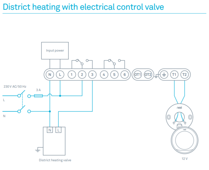
Wiring-Existing Flair System. Wiring-Typical 4-zone system.
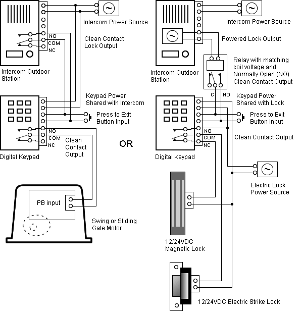
Dimension-Two-Way On-Off Low Voltage Valve. Honeywell Thermostat Wiring Diagram 4 Wire Examples The table above provides a more complete list of Honeywell thermostat wiring colors and their uses.
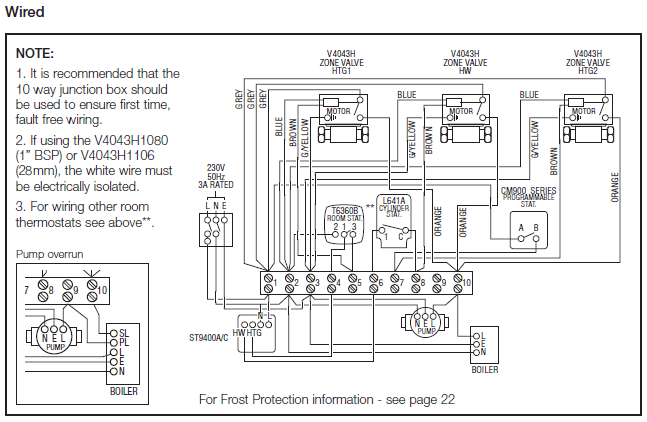
But here is a list of the most common wire color mappings, as seen in many four wire t-stat setups. Honeywell VE – 3/4″ NPT Connection Zone Valve, normally closed, Cv (24v) – Two-way on-off low voltage valves consist of an actuator and valve assembly for controlling the flow of hot water.
Use this valve in closed loop hydronic systems that do not contain dissolved oxygen in system water, such as fresh water from frequent source of makeup water.Wiring Zone Valves V 80 43 – Wiring Diagram SchematicsWiring Diagrams – Honeywell UK Heating Controls